
Complete manual
Every workflow, in detail
Instructions for version 0.5.8. Earlier releases may have different controls; use Help → Check for updates in your direct-sale app, or Microsoft Store updates for the Store edition.
Microsoft Store edition: Microsoft handles licensing, installation and updates. Explorer model thumbnails are unavailable in this edition; in-app previews remain available.
Use STL Workbench to design and edit solids, place artwork on an imported model, assign material regions, prepare an aligned multi-material assembly and export it to a slicer. Processing happens on your computer. The Design, Materials and Print workspaces share the same project. Open accepts STL, closed multipart 3MF and editable MDP projects.
This practical guide explains controls, values, steps and results. The images show real projects in the application. Select an image in the in-app manual to enlarge it. Search by a button label, task or setting, such as “Fill enclosed area”, “radius”, “Bambu”, “supports” or “export”.
1. Your first project
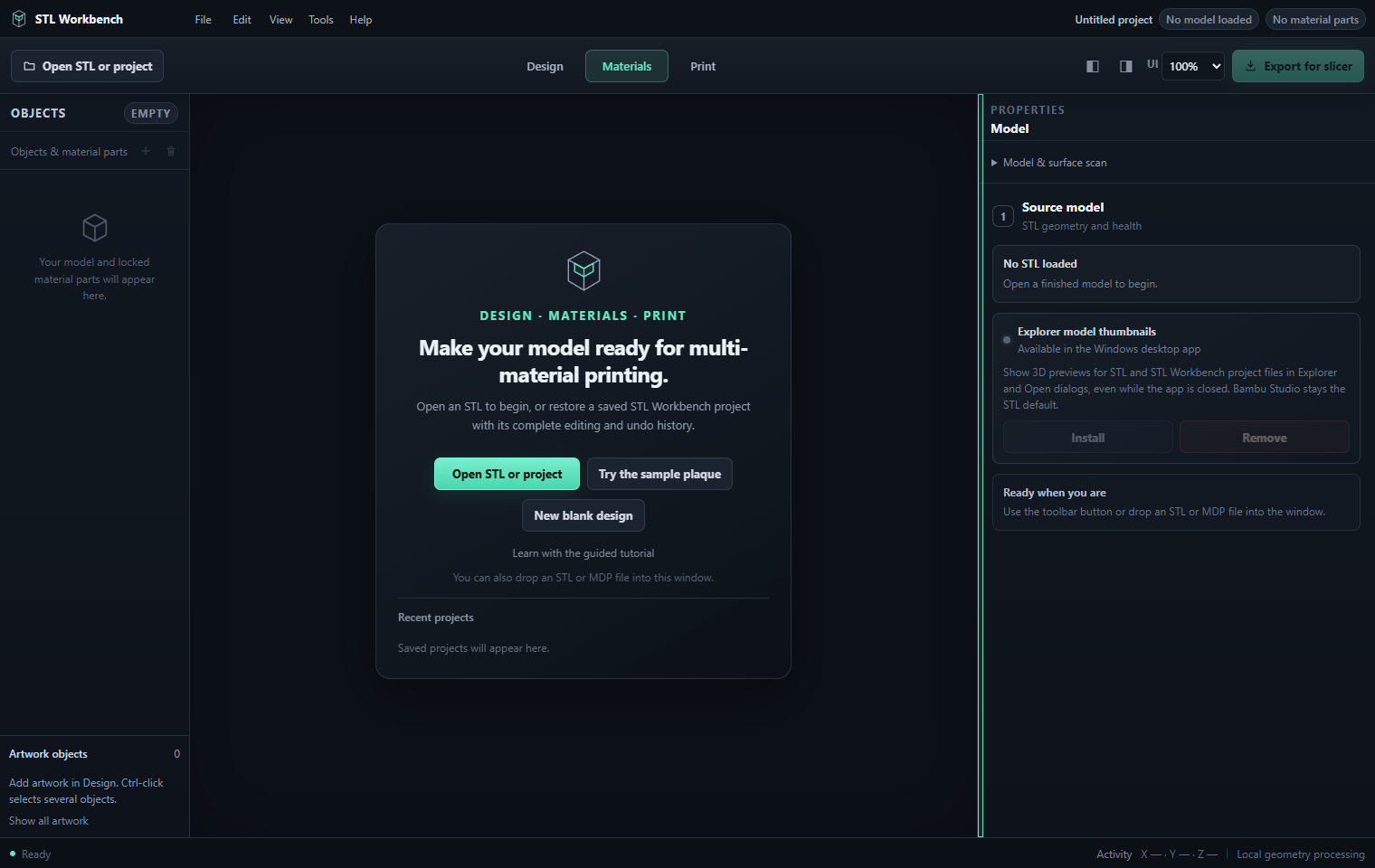
- Choose Open STL or project, or Try the sample plaque on the start screen.
- Wait for the model to load and its surfaces to be detected. Check the displayed dimensions before continuing.
- Choose a work surface from the model.
- Use Design to place a drawing or editable text, or use Materials to assign detected surface patches.
- Create material parts and review the result in Print.
- Save an MDP project so you can continue editing later. Export a 3MF assembly for your slicer when the parts are current.
Help > Guided tutorial follows these real tasks. A tutorial step is completed only when the project contains the corresponding result. Loading a sample follows the same import process as opening your own model.
In the in-app manual, the left contents highlights the chapter at the top of the reading area as you scroll. Its current entry stays visible without moving the article or keyboard focus. Select a chapter to jump directly to it. Search shows matching chapters; clearing the search or reopening the manual returns to the beginning.
First-project recipe
- Choose Try the sample plaque. This supplies geometry; the tutorial still checks your own results.
- Choose Top, then Choose work surface and click a flat area of the plaque. Check Current surface.
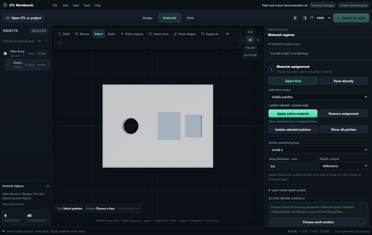
- In Materials, choose Select first, click a patch, inspect its outline, then Apply active material. The assigned counter increases after application.
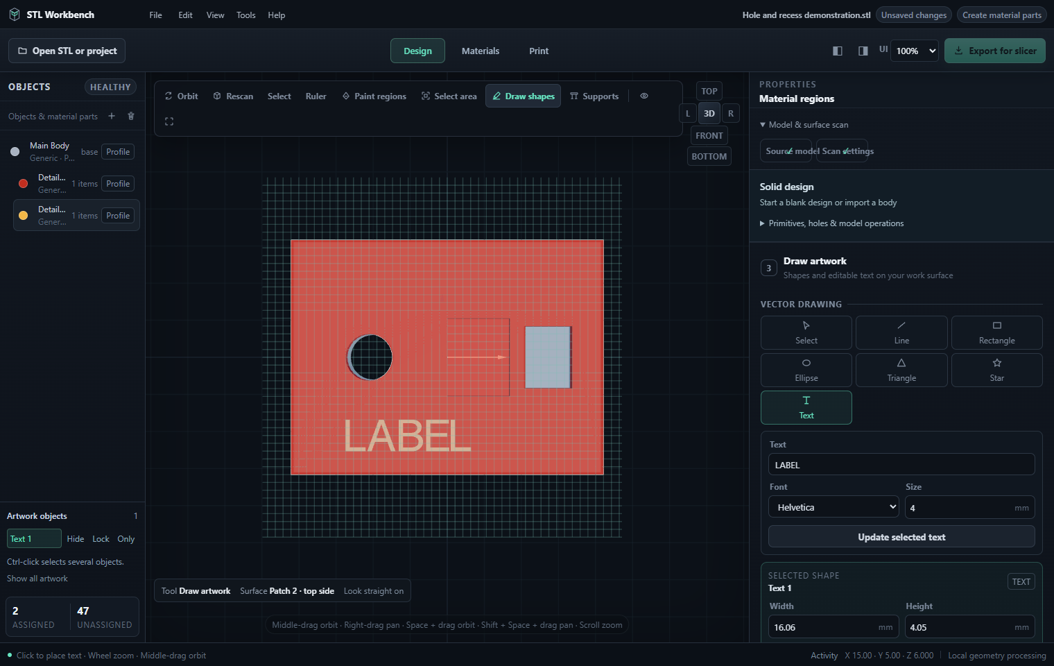
- In Design, choose Rectangle and drag on a clear part of the surface. It uses the active material; keep it clear of other materials' artwork.
- In Print, choose Create material parts. Wait for Exact volume and the watertight part count. Inspect the part boundaries.
- File → Save project preserves an editable MDP. Wait for Saved, then use Export for slicer, review material slots and export a 3MF.
Selection previews a possible assignment; Apply commits it; Build creates printable volumes; Save preserves editing; Export sends the current manufacturing result to a slicer.
2. The three workspaces
Design contains vector artwork tools and a separate Solid design section. Artwork includes lines, rectangles, ellipses, triangles, stars, editable text and imported outlines. Solid design includes primitive bodies, numeric transforms, holes and Boolean operations. Ordinary material artwork is not automatically a standalone CAD solid.
Materials contains selection preview, explicit material application, rapid surface-patch painting, area selection, material groups, inlay depth and part creation. Choose the active material before applying an assignment.
Print contains generated-part validation, orientation, dimensional checks, previews, support preparation and export settings. A generated assembly must reflect your latest document edits before export.
The object panel stays on the left, the model canvas in the centre and the contextual inspector on the right. Model & surface scan exposes source-model details and advanced detection settings.
Set up the printer before painting
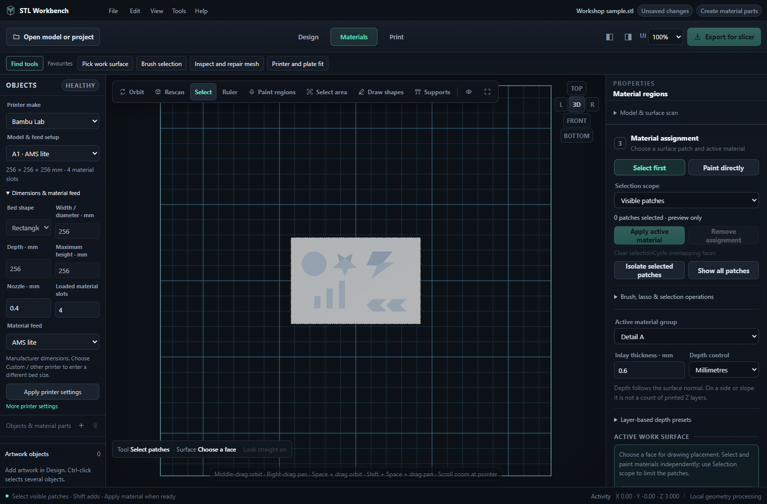
The Printer make and Model & feed setup selectors above the object list are available before opening a model. Choose the actual printer and its installed feeder configuration. For example, A1 · AMS lite starts with a 256 × 256 × 256 mm build volume and four material slots; A1 · External spool describes a different feed setup on the same printer. Selecting a known setup applies it immediately. Expand Dimensions & material feed to review the nozzle and loaded slot count, then use Apply printer settings after changing those fields.
The ordinary canvas then shows the configured printer plate boundary and grid. This helps judge scale while editing. More printer settings opens the advanced Print controls; final fit checks still happen on the complete manufacturing assembly. Printer setup, project material identity, a physical spool location and a numbered slicer filament are separate choices. Set the material assignment in Material profile before painting, and review it again at export.
The Windows desktop Detect printers & loaded materials button below this setup opens a separate, read-only connection dialog. It can also be opened from Printer assignment in the material editor. Discovering an address does not select the bed, authenticate a printer or assign material automatically. Read the device, then explicitly choose whether to use a recognized printer setup or one of its reported material slots. Chapter 16 explains pairing and reading provenance.
Find the appropriate control
| Area | Contents | Example |
|---|---|---|
| Design | Drawings, local placement, editable solids and mesh editor | Place a label or design a body with a hole |
| Materials | Patch selection, painting, profiles and inlay thickness | Assign two areas to different filaments |
| Assembly checks, layer previews, supports and export | Check thin lettering before choosing slicer slots | |
| Objects | Source/body, material parts, artwork and design objects | Select a drawing or Boolean child |
| Model & surface scan | Dimensions, mesh health and detection settings | Confirm scale or change patch segmentation |
| Header/status bar | Saved state, build state and latest activity | Identify unsaved edits or an outdated build |
| Printer setup above Objects | Printer make, model, actual build volume and feeder capacity | Select A1 with AMS lite before choosing material numbers |
Select a section heading to expand it. The inspector follows the workspace and tool. Choose Design and Draw shapes if the drawing palette is absent. Build an assembly before using manufacturing previews or export.
3. Opening models and checking scale
Open STL or project accepts an STL source model or an MDP project. The File menu also offers separate open commands. You can drop a supported file into the application window.
STL stores geometry without a standard unit declaration. Workbench uses millimetres. Review the model dimensions and correct an incorrectly scaled source before committing artwork or print preparation.
An MDP project restores the source, material information, drawings, relevant settings and editing history. Opening another document should preserve the current document until the replacement has passed its import checks. Save your work when prompted before replacing an edited project.
Import and inspect
- Use Open STL or project, a File open command or a dropped local file.
- Wait for import/detection. Read Source model for dimensions, triangle counts and health findings.
- Check a known dimension: a 20 mm calibration cube should measure about 20 mm.
- Inspect several sides. Open edges, disconnected shells or non-manifold shared edges can prevent valid material partitioning even when inspection is possible.
To change scale in the design workflow, start a blank design, use Add STL body, select it and set its X/Y/Z Scale multipliers before Apply design to model. A multiplier of 2 doubles that axis. A 25.4 multiplier converts coordinates intended as inches into millimetres. Check all three resulting dimensions. Perform source-scale changes before surface artwork where possible, because changed geometry can require its references to be resolved again.
Explorer thumbnails
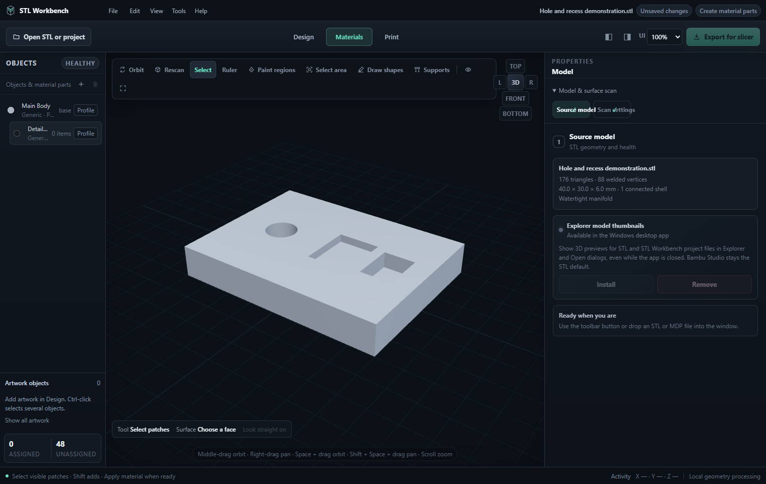
The Windows desktop Explorer model thumbnails card can install or remove the preview provider. Install enables STL/MDP thumbnails in Explorer and Open dialogs while Workbench is closed. Remove unregisters the provider. Installing does not choose another default STL-opening application.
4. Saving, recovery and recent projects
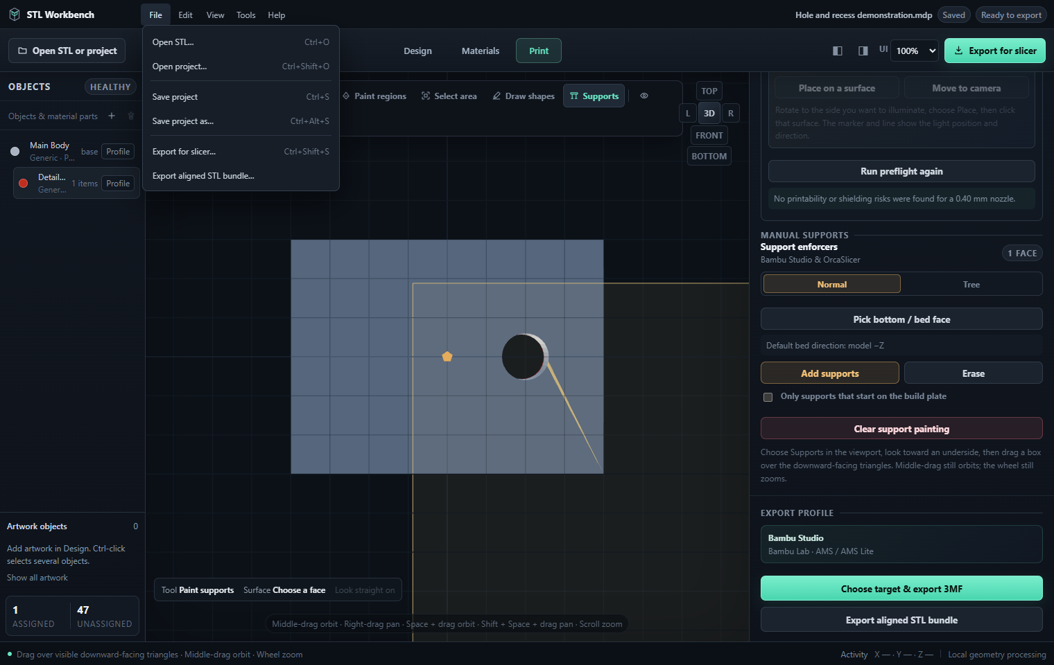
Use File > Save project or Ctrl+S to save an editable MDP document. Save project as creates another project file. A slicer export is a manufacturing handoff, not a substitute for the editable project.
The header shows the project name, saved or modified state and the status of generated material parts. Unsaved changes refer to document edits; camera movement and workspace navigation do not need a new geometry build.
Recent projects appear on the start screen after projects have been saved or opened. If a recovery snapshot is available after an interruption, the start screen offers Recover project. Review the recovered result and save it to a project file. Recovery does not replace deliberate saves or external backups.
Save and restore
| Command/state | Meaning |
|---|---|
| Save project | Writes editable source, current state and Undo/Redo to MDP |
| Save project as | Uses another filename for a copy or variation |
| Saved | The current document revision was written successfully |
| Unsaved changes | Current edits still need saving; a saved older snapshot can leave this state visible |
| Recent projects | Reopens a saved/opened MDP; use Open project if it moved |
| Recover project | Restores the available interruption snapshot for review and saving |
Desktop saving uses a local file dialog; browser saving downloads an MDP. Use meaningful names such as plaque-front-v2.mdp. When replacing or closing edited work, Save preserves it, Discard changes accepts losing unsaved changes and Cancel returns to editing. Exporting STL/3MF does not mark the editable project saved.
Example: save before changing inlay depth, then Save project as for the deeper version. Both files retain their respective editable objects and histories. Wait for the saved state before closing a large project.
5. Viewing and navigating
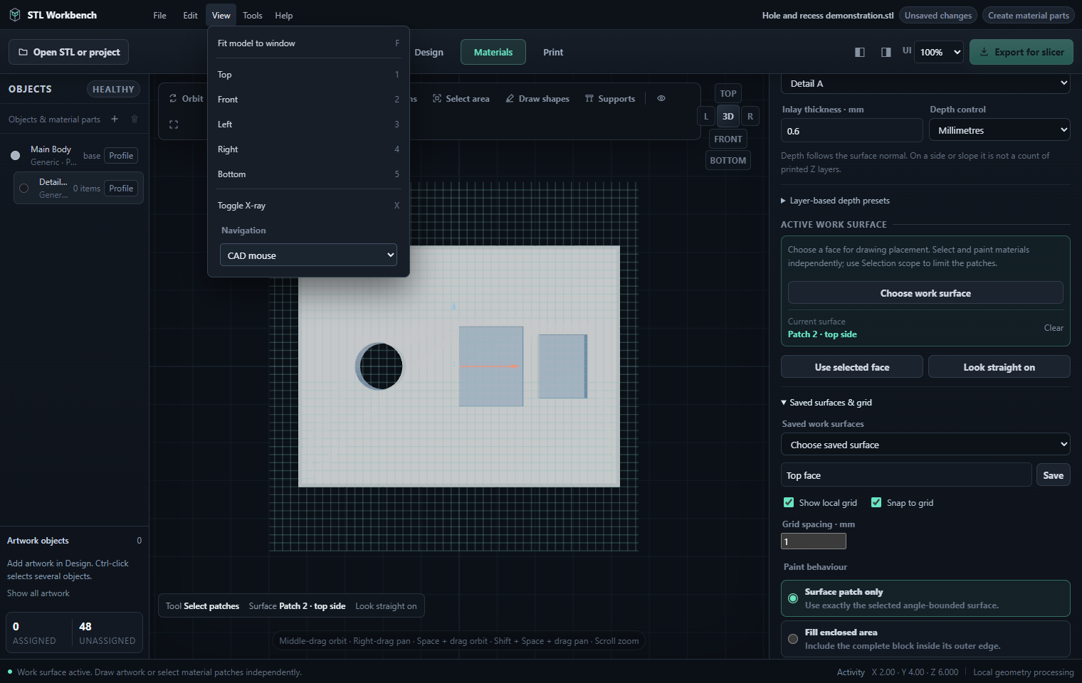
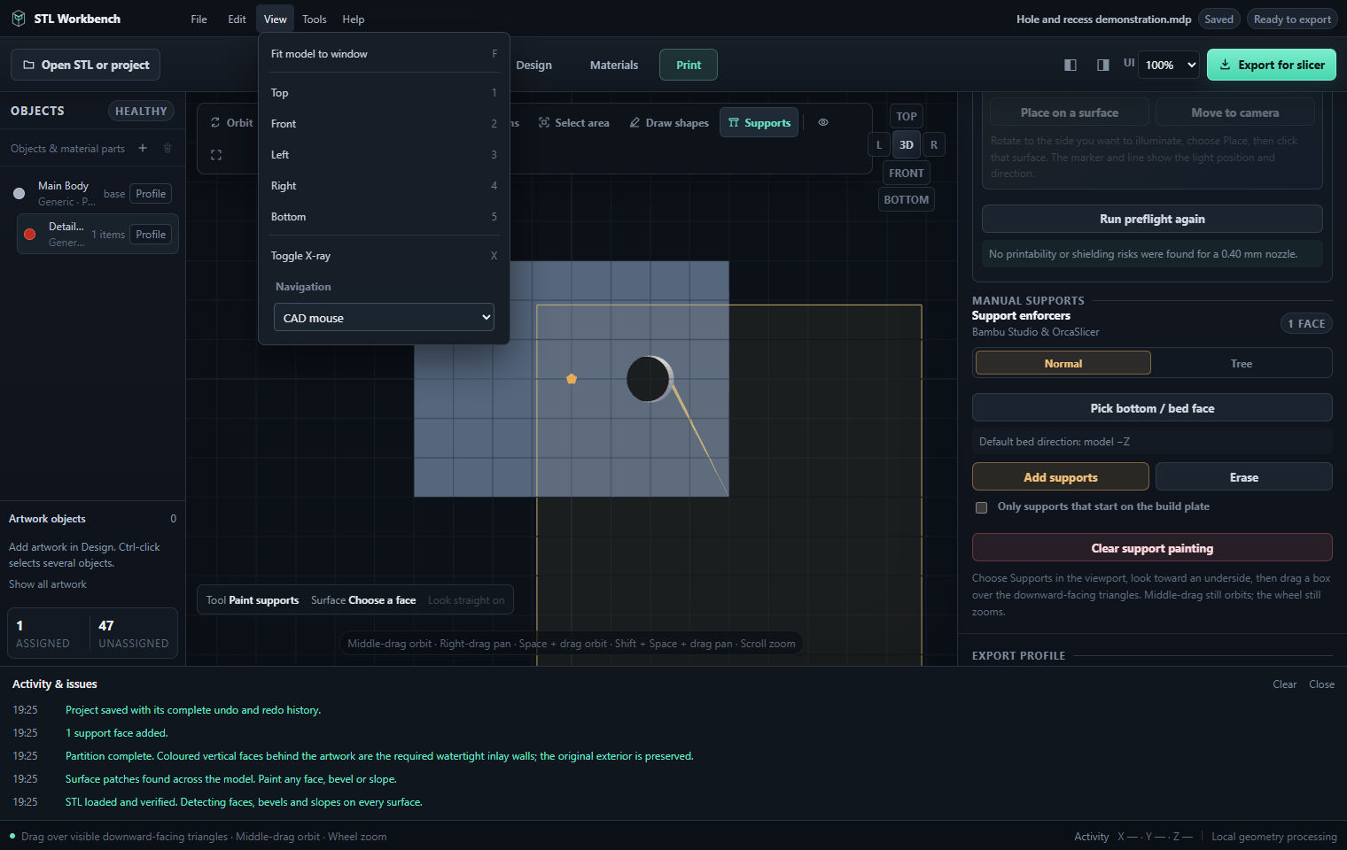
Use the named Top, Front, Left, Right and Bottom views to inspect different sides. Fit model to window brings the complete assembly into view. X-ray helps reveal internal or obscured geometry.
View → Navigation chooses a saved gesture preference shared with Rebuilder. CAD mouse uses middle-drag to orbit and right-drag to pan. Right-drag orbit swaps those two gestures. Trackpad / two-button provides Space + left-drag to orbit and Shift + Space + left-drag to pan. Those Space gestures work from any editing tool. In Orbit/Inspect, ordinary left-drag orbits and Shift + left-drag pans.
The wheel or two-finger vertical scroll zooms towards the mouse pointer. Point at the area you want to inspect before scrolling; it does not need to be in the centre of the viewport. This applies in both the main workspace and the feature editor. Pan moves the view horizontally and vertically; it does not change model X/Y coordinates. For trackpad panning, use Shift + Space + drag rather than assuming horizontal scrolling moves the model. Editing tools reserve ordinary left-click for their operation. Follow the current canvas hint and release Space before editing again.
Use Look straight on after choosing a work surface to inspect it without perspective skew. Tool, active surface and build status are displayed so you can confirm where an operation will apply.
View controls
| Control | Effect |
|---|---|
| Named views | Change camera direction; keep the chosen surface and geometry |
| Fit model | Recentre and frame the model/assembly |
| X-ray | Reveal obscured geometry without cutting or removing it |
| Orbit | Reserve ordinary left-drag for viewing |
| Look straight on | Align the camera to the active work surface |
| View → Navigation | Save the preferred mouse/trackpad gestures locally |
To reach a back face, use Orbit or hold Space from an editing tool, rotate, release Space and resume editing. Shift + Space + drag pans. Pan changes the camera target; it does not change object Local X/Y or solid Position coordinates. While typing in a field, camera shortcuts leave normal text editing available.
Rotation and panning follow the pointer directly, without inertia or a settling delay. The view stops when the pointer stops, even while the mouse button is held. This applies to all navigation presets in both the main workspace and the feature editor.
6. Choosing a work surface
Choose work surface in the inspector, then click the flat face you want to use. Top, underside, side and angled planar faces can all define a local drawing plane. Rotate the model first if the face is hidden.
A work surface defines placement and its local coordinates. It should remain distinct from selection scope and recessed-depth filters. Changing the camera does not change the surface. Changing the work surface should retain material assignments already made elsewhere.
Read the Current surface value before drawing or assigning a region. Use Clear to remove an explicit surface choice when appropriate. A named face or patch is a reference to detected geometry, not a claim that the whole model is flat.
Select one patch and choose Use selected face to make it the work surface. Look straight on aligns the camera to that face. Saved surfaces & grid lets you name the active surface, return to a saved one, display its local grid and set snapping spacing in millimetres. Compact coloured arrows show the local-axis directions. Large grids may display major multiples of the snapping interval to remain readable.
Selected patches have solid boundary outlines; the hovered patch has a dashed outline. Internal triangle edges are omitted, so the outline describes the detected patch. Isolate selected patches temporarily hides other source patches for inspection and picking. Show all patches restores them. Isolation changes the view only; it does not edit assignments or invalidate a material build.
Name a side face and use its grid
- Select one patch and Use selected face, or Choose work surface and click it directly.
- Look straight on aligns the view to that face, including a side or slope.
- Expand Saved surfaces & grid, name it
Front labeland choose Save. - Enable Show local grid, optionally enable Snap to grid and set Grid spacing · mm. Try 1 mm for general layout or 0.5 mm for a small icon.
- Return using Saved work surfaces. Clear removes the explicit work-surface choice.
Spacing is local to the surface, independent of printer Z layers. On large faces, visible major lines can be farther apart than the snap interval for readability. Cycle overlapping faces inspects candidates under the last pick. Check their outline before making one the work surface. Isolate selected patches assists inspection; Show all patches restores the complete source view.
7. Surface detection and rescanning
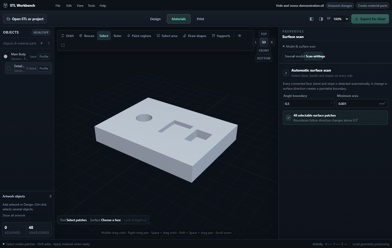
The automatic scan groups connected triangles according to changes in surface direction. Angle boundary controls the allowed directional change. Minimum area removes patches too small for the current task.
Keep the default scan settings for a first project. Very small thresholds can create many patches; large thresholds can merge detail you wanted to select separately.
Rescanning changes the detected patch structure. Review the proposed result and any remapped or unresolved assignments before applying it. Do not assume an old numeric patch label describes the same geometry after a rescan. Use Undo if an applied scan change produces the wrong result.
Scan values and their effects
| Setting | Effect of increasing it | Typical task |
|---|---|---|
| Angle boundary | Allows more change of direction inside one connected patch | Reduce tiny patches on a faceted curve cautiously |
| Minimum area · mm² | Omits smaller selectable candidates | Reduce it to expose a small letter/detail |
| Rescan | Computes a proposed interpretation with the chosen settings | Review patches and remapped references before accepting |
Change one value at a time. Low area thresholds increase candidate count; high angle allowances can combine details you wanted separately. Review the rescan proposal and resolve its findings, then accept/apply it or cancel to keep the previous scan. Undo can restore an accepted earlier interpretation. Rescanning does not repair an open mesh or resize it.
8. Drawing artwork
Choose Design or Draw shapes. The drawing palette appears in the contextual inspector. Select a shape tool, then draw on the chosen work surface. Hold Shift where indicated for a square or circle.
Select mode picks an existing drawing. Drag its box to move it, corner handles to resize it and the circular handle to rotate it. Use Width, Height and Rotation for exact values. Duplicate creates another drawing; Delete removes the selected drawing.
For a line, set Line thickness and its circular or square ends. These values describe the artwork footprint. Material depth is controlled separately.
Artwork must intersect a suitable part of the model. A drawing placed outside the source or spanning unsupported geometry may produce no valid material volume. Inspect the generated result before export.
Shape tools and exact size
| Tool | Creation/setting |
|---|---|
| Select | Pick artwork; drag its box, resize handles or rotation handle |
| Line | Drag endpoints; set footprint thickness and Circular/Square ends |
| Rectangle | Drag opposite corners; Shift makes a square |
| Ellipse | Drag a bounding box; Shift makes a circle |
| Triangle | Drag the area of an isosceles triangle |
| Star | Drag the area of a five-point star |
| Text | Enter words/font/size, then place editable text |
Selected Width/Height are local-plane millimetres. Rotation is degrees within that plane. Material assigns its insert to a material group. A 12 × 8 mm rectangle rotated 30° changes its direction on the surface; material depth remains separate.
For a line, the 0.2–30 mm Line thickness field describes footprint width. Try 2 mm with Circular ends, then use the selected drawing's dimensions for precise placement. Check small features against the printed line width in Print. Duplicate creates editable artwork; Delete removes it. Geometry edits require a material rebuild.
9. Editable text
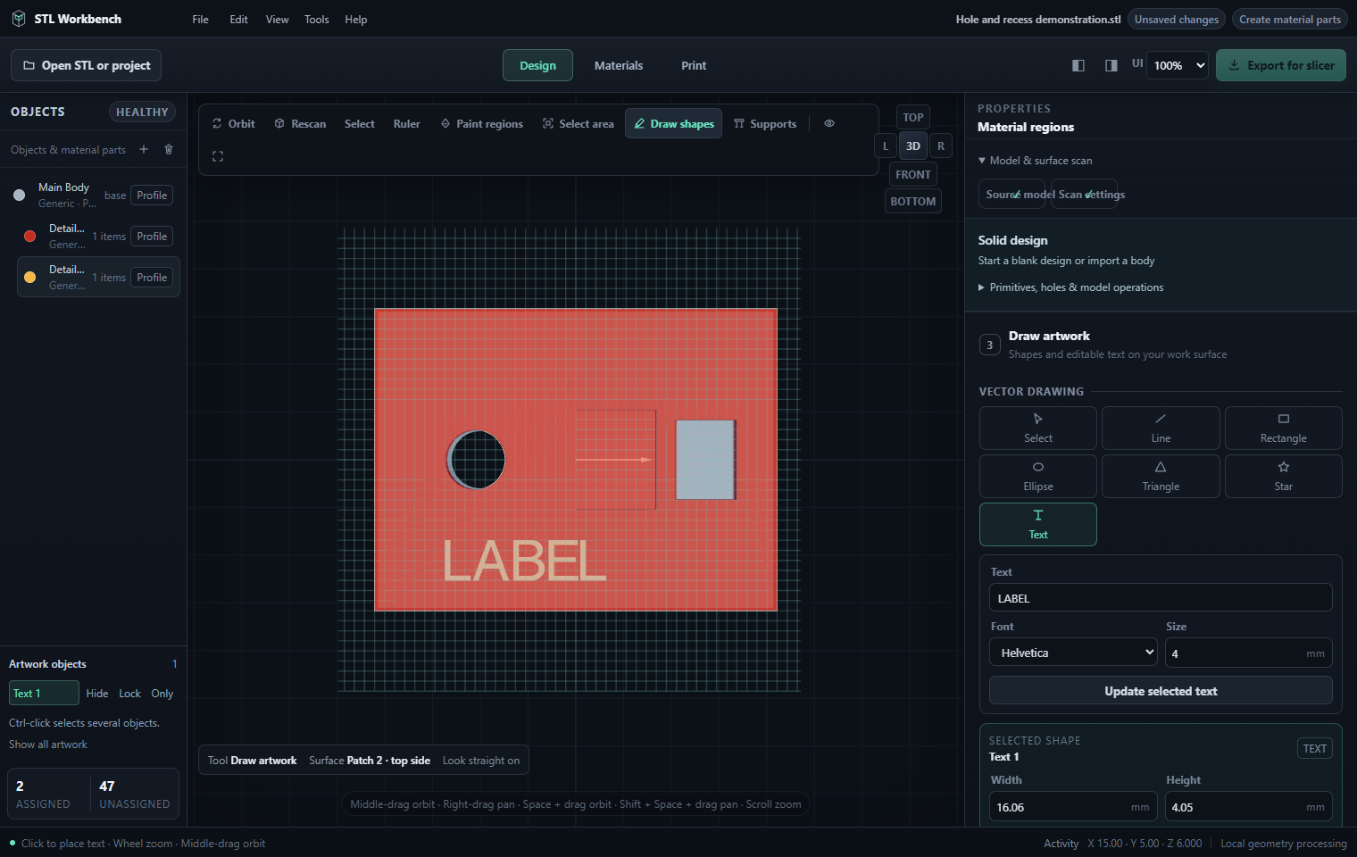
Choose Text in the drawing palette. Enter the text, choose a font and set its size in millimetres. Place it on the work surface.
Select an existing text object and use Update selected text to commit text, font or size changes. Width, height, rotation and material are available on the selected drawing card.
Small lettering can exceed what your printer or nozzle can resolve even when the geometry is valid. Use dimensional checks and review the sliced toolpaths for thin strokes, small islands and narrow gaps.
Place and revise a label
- Choose Text, enter up to 80 characters and set Size · mm. The field offers 1–100 mm; try 6–8 mm on the sample.
- Select Helvetica, Helvetica Bold, Optimer, Optimer Bold, Gentilis Serif or Gentilis Serif Bold. Bold fonts provide broader strokes.
- Click the work surface to place it. Select the text object and refine Width, Height, Rotation and Local X/Y.
- To revise words, font or size, select the existing text and choose Text in the palette to reveal its text fields. Change those fields and choose Update selected text. Inspect the new outline and position.
- Build and check fine lettering against nozzle/printed line width. Increase size or stroke width if the findings show unprintable islands.
Font size scales the outline; actual capital height and word width depend on the font. “WORKSHOP” and “IT” at the same size have different widths. Changing Width/Height can stretch the object, so choose the font size first when proportions matter.
10. Material groups and inlay depth
Select an Active material group before painting. The Objects panel lists the source and material parts; Add material group creates another assignable material definition.
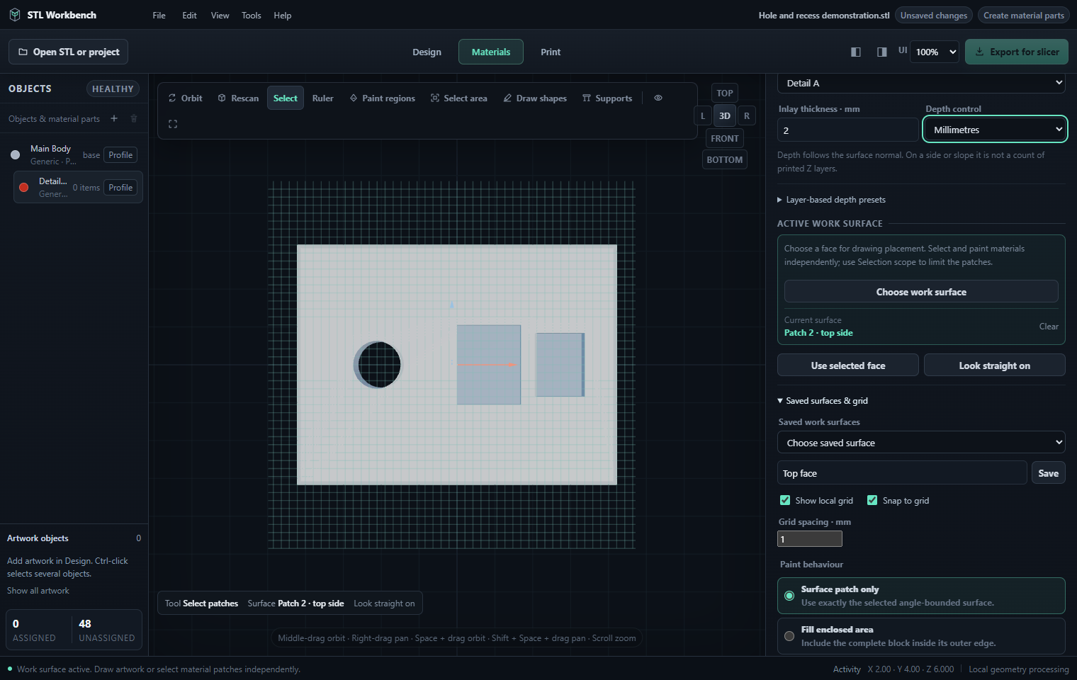
Inlay thickness is measured into the model normal to the selected surface. Use Inlay thickness · mm for a direct depth. Depth control chooses Millimetres or Layer preset. The Layer-based depth presets section retains existing projects' layer settings; its resulting depth equals material layers multiplied by the configured layer height. On a side or angled surface this is a depth normal to that surface, not a literal count of printer Z layers.
Choose a depth that fits within the available source thickness. Thin walls, neighbouring inlays or large depths can leave little base material. Generated-volume validation and dimensional checks help identify these cases.
Edit a material profile to set its name, display colour, manufacturer references and physical or optical values. These describe the material and preview; they do not guarantee a physical print will match the display.
Create, change and delete a material
- Add material group beside Objects & material parts creates a detail material. Choose it in Active material group.
- Choose direct thickness or Layer preset. In Layer-based depth presets, 3 layers × 0.20 mm produces 0.60 mm depth.
- Open that group's material editor from its object row, select a library profile or enter its identity/display colour, then save the form.
- Assign patches or drawings. The base/body is the source volume remaining after the inserts are cut out.
| Setting | Meaning | Example |
|---|---|---|
| Millimetres | Direct depth into the applicable surface | 0.6 mm shallow label |
| Layer preset | Material layers × project layer height | 4 × 0.20 = 0.80 mm |
| Planar depth | Along surface normal | Side-face label cuts sideways |
| Cylindrical depth | Radially inward | Curved label follows the exterior |
Changing the active material selects the target for subsequent actions. Changing an assigned thickness changes printable geometry and needs rebuilding. Choose profile values to describe the actual spool.
Delete selected material, beside the + button, removes the selected project detail material. It does not delete a catalogue profile. The base is protected, and the last remaining detail material cannot be deleted. For a used material, the confirmation lists its patch/artwork/solid usage. Choose another detail material as replacement, or explicitly remove assignments and artwork while using base for solids. Cancel preserves the document; confirmed deletion can be undone.

11. Assigning surface patches
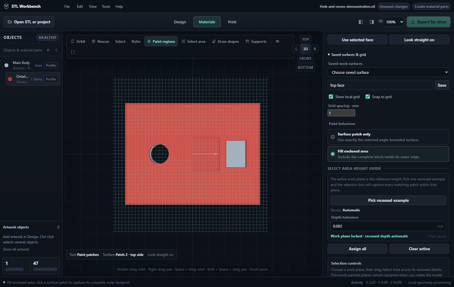
Use the patch-painting tool for direct assignment to the active material. Surface patch only uses the selected angle-bounded patch. Fill enclosed area attempts to include the complete connected block within its outer boundary.
Select first highlights patches without assigning them. Choose a Selection scope: Visible patches, Current work surface, Connected surface, Coplanar patches or Matching recesses. Inspect the selection count and highlight, then Apply active material. Remove assignment clears material from those selected patches; Clear selection leaves the document's assignments intact.
After picking a face, Cycle overlapping faces moves through other candidates under that last pick. This helps when an obscured face lies behind the visible one. Confirm the highlighted result before making it a work surface or applying a material.
Paint directly is the separate rapid assignment tool. The selection highlight represents a preview, not a committed material colour.
Alt-click removes an assignment in the existing patch-painting workflow. Clear active removes assignments for the active material. Assign all applies the active material to the applicable unassigned regions; check its scope before using it.
Select first
- Choose the active material and thickness, then Select first.
- Choose a scope, click a patch and inspect the selection outline/count. Add to the selection with the supported modifier gesture.
- Apply active material commits it. Remove assignment clears materials from selected patches. Clear selection clears the temporary selection only.
| Scope | Appropriate task |
|---|---|
| Visible patches | General picking of visible patches |
| Current work surface | Limit the task to the chosen reference |
| Connected surface | Expand through the connected surface relationship |
| Coplanar patches | Work with a shared planar reference |
| Matching recesses | Use work surface and recessed-depth guide |
Paint directly and Fill enclosed area
Paint directly / Paint regions commits the active material while picking. Surface patch only uses that detected patch's footprint. Fill enclosed area uses its enclosing footprint and clips depth against the actual body. A through-hole stays open: the preview tints existing source surfaces instead of drawing a fictitious flat face across it. Recess floors are affected only when inside the applicable footprint and insert depth.
Example: paint a plaque with a through-hole using Fill enclosed area at 0.6 mm depth. Inspect the opening and Build to confirm closed inserts and the remaining body. Increase depth only if you intend to reach deeper recess surfaces.
Assign all applies the active material to applicable unassigned patches under the current scope/filter. Clear active removes the active material's patch assignments. Inspect scope first when different sides contain different designs.
12. Selecting recessed details
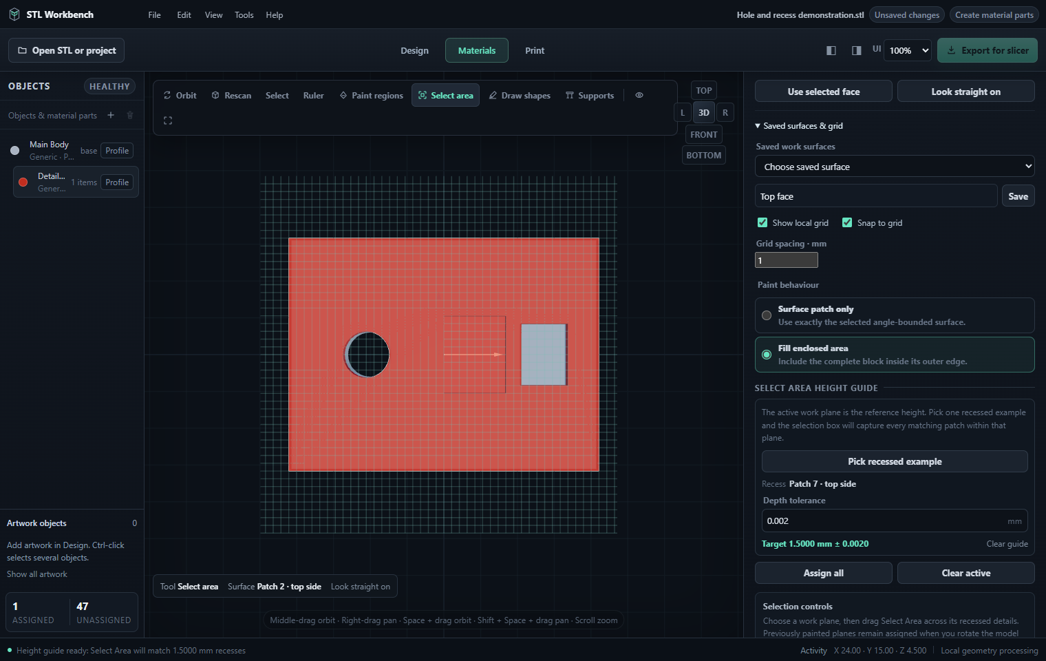
Select Area uses a dragged selection box for suitable surface patches. For recessed-detail matching, choose the reference work surface and then Pick recessed example.
The example supplies a depth behind the reference plane. Depth tolerance controls how closely other patches must match it. A small tolerance is precise; a larger tolerance includes more depth variation.
Recessed selection is useful for lettering or panels cut into one plane. It is different from general artwork placement. Clear guide removes the example depth. Previously assigned regions remain part of the document when you work on another side.
Match several recessed letters
- Pick the surrounding flat face as the work surface.
- Pick recessed example, then click a representative recess floor rather than its vertical wall.
- Check the guide summary. Start with Depth tolerance 0.002 mm; the field offers 0.0001–1 mm. Increase it only if intended details have small depth differences.
- Use Matching recesses or Select Area, drag across the intended details and inspect the resulting selection.
- Apply material and inspect another angle. Clear the guide before unrelated depth/face tasks.
Tolerance is the permitted difference from the example depth. It does not thicken inserts or enlarge a selection box. A 0.01 mm tolerance may include floors differing by 0.005 mm, while excluding a panel 0.5 mm deeper. Set inlay thickness separately.
13. Creating and checking material parts
Create material parts evaluates the assigned patches and drawings against the source mesh. The output consists of watertight material volumes and the remaining body, aligned in a shared coordinate system.
Inspect the exterior and the part boundaries. Coloured vertical walls behind flush artwork can be the interior walls needed to close a watertight inlay; they are not necessarily unwanted changes to the exterior.
Document edits that affect geometry or depth make the last generated build stale. Rebuild after those edits before exporting. Workspace changes, tool changes and inspection should preserve the last valid assembly.
Review validation findings rather than relying only on appearance. Open geometry, overlaps, insufficient volume or unresolved dependencies need attention before slicing.
Build and inspect
- Finish solid changes with Apply design to model and resolve artwork on changed source surfaces.
- Choose Create material parts / Generate locked parts. Keep the document unchanged or cancel deliberately.
- Review Body + inlays: Exact, Watertight parts and preflight issues.
- Explode inspection separates parts visually. Return it to 0 for fit inspection; export preserves locked coordinates.
- Rebuild after source, footprint, assignment or thickness changes. The header indicates when the current build is stale.
Cancel retains the last valid assembly. Undo or replacement during a build prevents an outdated result from replacing newer work. When final commitment has begun, let it settle and then use Undo/rebuild for changes.
For a simple 20 × 20 × 10 mm box, volume is 4000 mm³. A full 0.6 mm top insert occupies 240 mm³ and leaves 3760 mm³ before holes/other inserts. Workbench verifies the computed partition; a coloured footprint alone does not establish closed-volume validity.
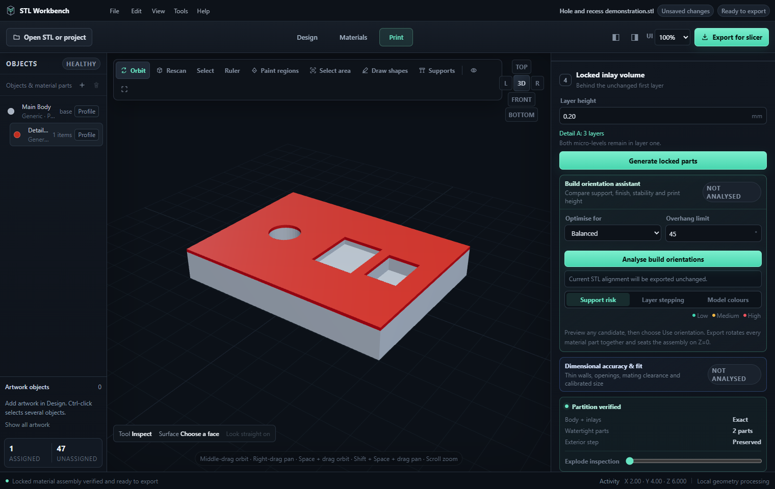
14. Orientation and dimensional checks
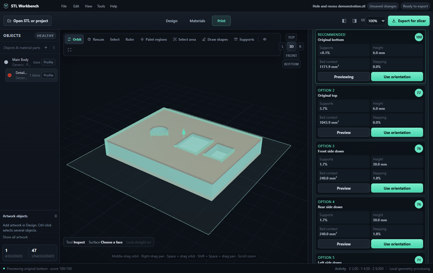
Analyse build orientations compares candidate bed directions. Review the suggested contact area, support requirement and other findings, then choose an orientation appropriate for the intended part.
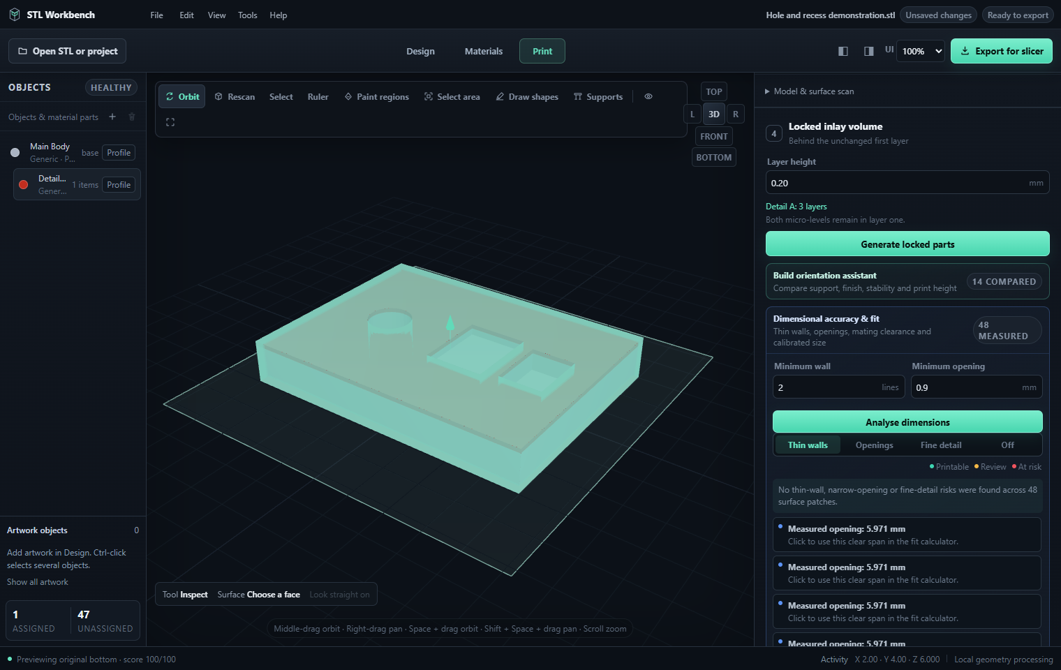
Analyse dimensions & fit measures detected features and reports dimensional risks. Click a finding to inspect the affected area. Dimensional export correction changes the shared exported geometry; it should be an intentional manufacturing adjustment.
All material parts must receive the same orientation and export transform so the assembly remains aligned. Review the final arrangement in your slicer.
Orientation settings
- Expand Build orientation assistant after building.
- Choose Optimise for: Balanced, Surface quality, Fewest supports or Bed stability. This changes the candidate ranking weights.
- Set Overhang limit, initially 45° within the 20–80° field, then Analyse build orientations.
- Preview a candidate and review bed contact, support risk, finish, stability and height.
- Use orientation commits the shared export orientation. Restore original STL orientation removes it.
Support risk and Layer stepping heatmaps highlight different concerns; Model colours restores material appearance. A candidate's view preview and its committed export orientation are separate actions. Export seats the transformed assembly on Z=0.
Dimensions, fit and correction
Set Minimum wall in printed lines and Minimum opening in millimetres, then Analyse dimensions. Two wall lines at 0.45 mm printed width imply about 0.90 mm thickness. Click a finding to inspect its location and choose Thin walls, Openings, Fine detail or Off.
For Selected opening fit, select an opening finding, choose Press/Snug/Sliding/Loose and enter Mating part size · mm. A 5.2 mm opening around a 5.0 mm pin has 0.2 mm total dimensional clearance; printing variation still affects fit.
For repeatable scale error, enter a calibration object's Nominal size and Measured X/Y/Z, then Apply correction on export. Nominal 20 mm measured as 19.8 mm in X gives a correction of 20 ÷ 19.8 ≈ 1.0101 in X. Every material receives the same transform. Remove correction restores uncorrected scale; correction does not remodel individual holes.
15. Printed, internal and light previews
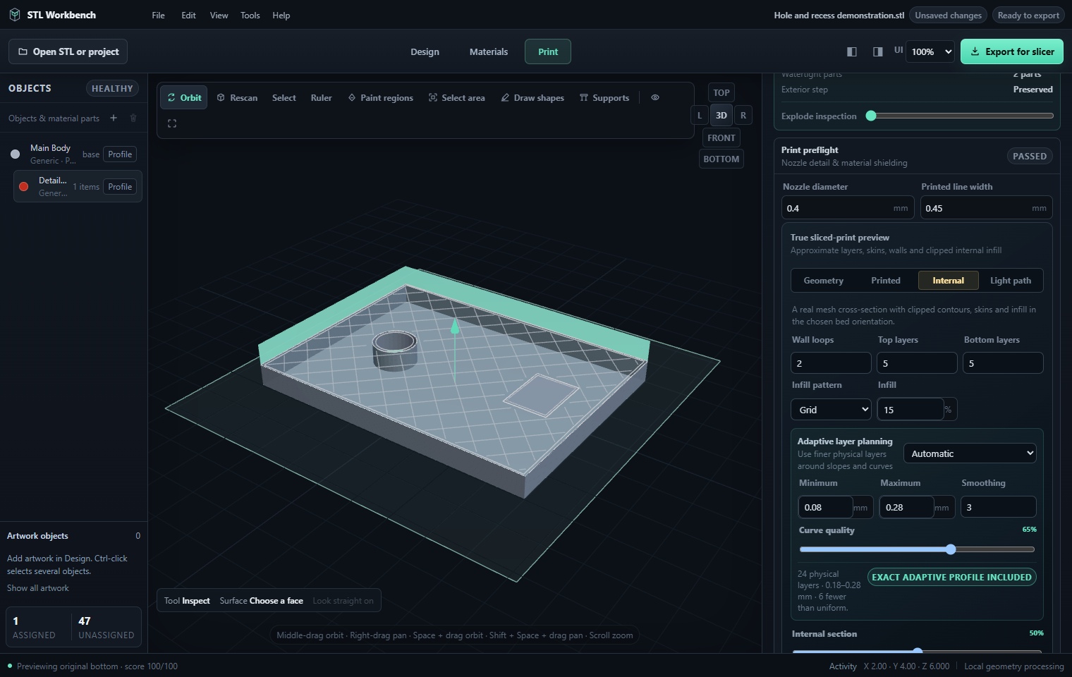
Printed view displays layer-related detail. Adaptive layer settings calculate a varying layer schedule where supported. Internal view helps inspect the relationship between the body and inlays.
Light inspection uses material transmission and diffusion settings together with geometry and lighting. Place the light from a model surface or the current camera direction.
Optical preview is an estimate. Filament thickness, colour, infill, walls, printer settings and illumination all affect the physical result. A calibrated profile is more informative than an unmeasured preset.
Preview settings and their effects
| View or setting | What to use it for |
|---|---|
| Geometry | Inspect the closed material parts without simulated printing |
| Printed | Compare visible walls, skins and infill with the selected print assumptions |
| Internal | Inspect a cut through the model; Section height sets the cut as a percentage of model height |
| Optical | Estimate transmitted light using material profiles, geometry and the inspection light |
| Walls | Number of printed perimeter lines; thicker shells can reduce transmission |
| Top / bottom layers | Number of solid skin layers; 0 removes that skin from the preview assumptions |
| Infill | Percentage, 1–100; Lines, Grid and Triangles change the previewed internal pattern |
- Build the material parts, then choose Printed or Internal.
- Enter the wall, top, bottom and infill values you expect to use in the slicer. For example, 2 walls, 5 top layers, 5 bottom layers and 15% Grid infill.
- Move Section height through 1–99% to inspect different internal heights. This is a viewport cut, not a geometry edit.
- Compare the exported file's imported settings and final toolpaths with these assumptions.
Adaptive layers
Off uses the normal layer height. Automatic derives a schedule from shape; Custom lets you choose Minimum and Maximum layer height, Smoothing and Surface quality. Higher quality and smaller minimum height request finer layers where shape needs them. Smoothing limits abrupt schedule changes. Inspect the calculated summary and transfer note: adapter support differs, and the slicer must confirm the imported schedule.
Inspection light and material shielding
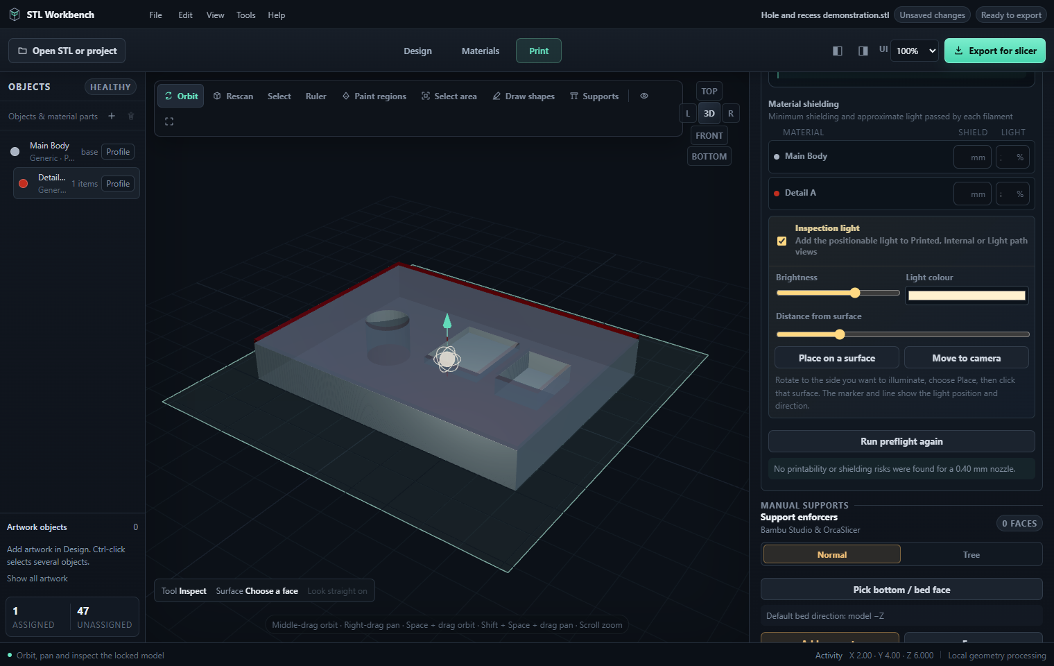
Enable Inspection light, then adjust Brightness (0–100%), light colour and Distance. Place on model picks a source surface for the light; From camera aims it from the current viewing direction. The marker and line show position and direction. Use a warm colour for an indoor lamp comparison, or a neutral colour to compare materials consistently. Distance changes the inspection-light placement relative to the model; it is not a measured lamp specification.
The per-material Shield value is the minimum desired shielding thickness in millimetres (0–20 mm); preflight compares it with the model. Light changes the approximate transmitted-light percentage (0–100%). These controls do not add or remove printable solids. Set transmission/diffusion in the material profile and calibrate a real swatch before relying on a subtle light effect.
Run print preflight
Enter Nozzle diameter (0.1–2 mm) and Printed line width (0.1–3 mm) to match your printer/slicer assumptions, then Run preflight again. A common starting comparison is a 0.40 mm nozzle with 0.45 mm lines. Review fine-feature, wall and shielding findings; select a finding to inspect the affected geometry. These are checks against entered assumptions, not proof that a particular printer has been configured correctly.
16. Filament library and calibration
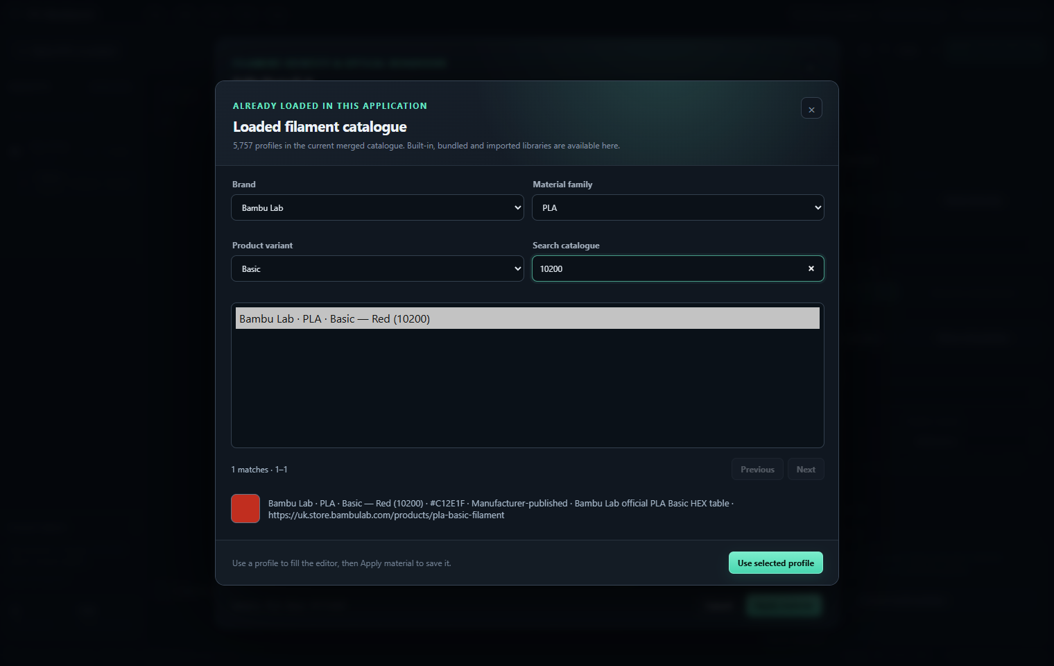
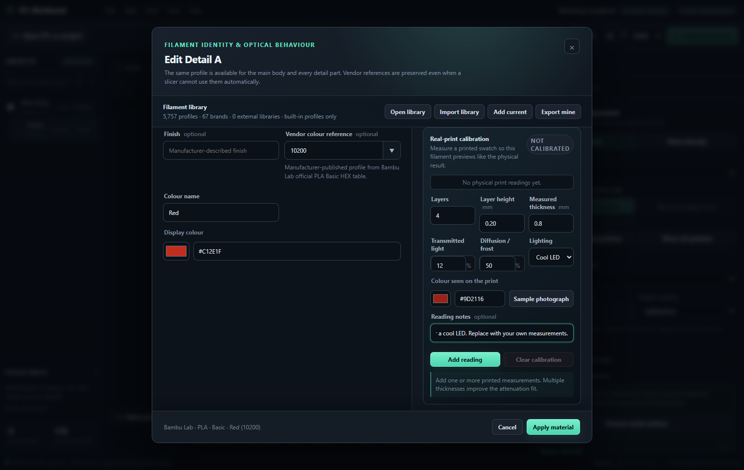
Open the material editor to search the bundled filament library by brand, material, colour, finish or reference. Use selected profile fills the editable material form. Add current saves a personal profile; Export mine writes your personal library.
A vendor colour reference is manufacturer catalogue information, not a universal colour standard. Check the spool and supplier before purchasing or substituting material.
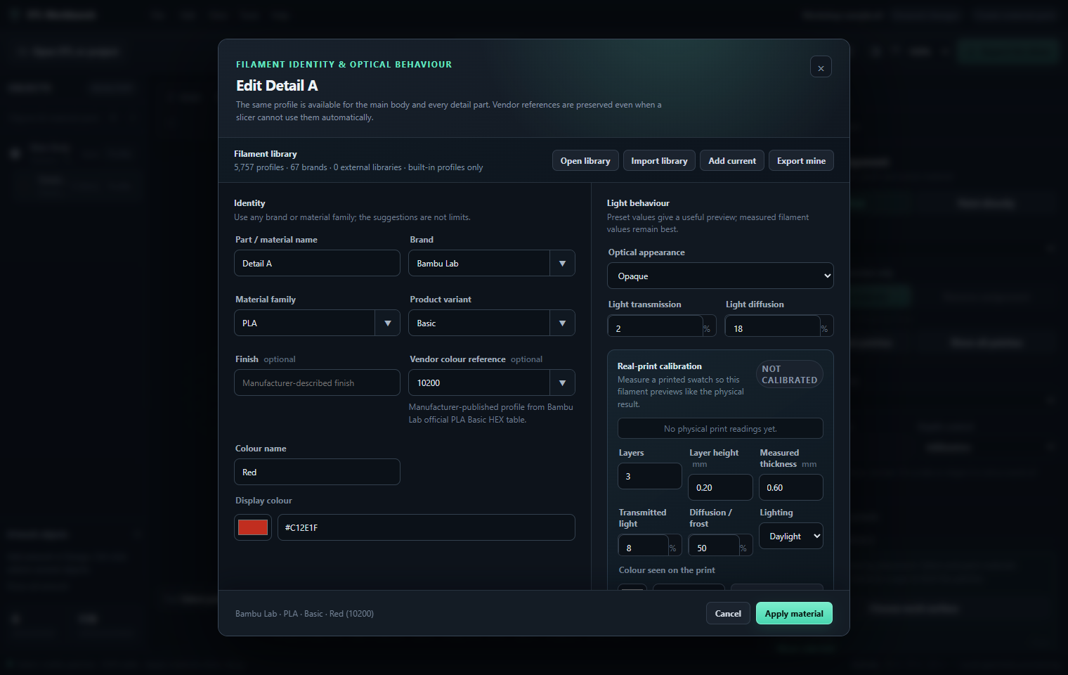
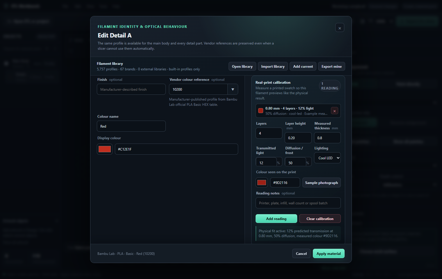
Real-print calibration stores measured swatches with layer count, layer height, thickness, transmitted light, diffusion, lighting and observed colour. Multiple thickness measurements improve the fitted attenuation model. Photograph sampling averages a small area; avoid glare and shadows.
Browse, import and choose profiles
- Select the base or detail material you want to edit and open Material profile.
- Choose Open library to browse the catalogue already loaded in the app. Filter Brand, Material type and Product variant, or search a name, colour or supplier reference.
- Select a result and read its source/details. Use selected profile fills the editable form; review it before saving.
- Import library loads an additional compatible local JSON library. This is separate from browsing. Add current stores the current form as a personal entry; Export mine downloads your personal library.
The catalogue combines official product ranges and manufacturer colour records with community swatches identified by their source. Coverage differs by brand and product. A product range without a verified colour can still be used with a custom editable colour; it is not evidence that every colour, spool or stock item has been verified.
Material profile fields
| Field | Meaning and example |
|---|---|
| Name | The name shown in this project, such as Red lettering |
| Brand / Material type | Manufacturer and polymer, such as Bambu Lab / PLA |
| Product variant | Supplier's product line, such as Basic; separate from Finish |
| Finish | Optional appearance description, such as matte or silk |
| Supplier reference | Vendor's code; Bambu Lab PLA Basic Red uses 10200 |
| Colour name / Hex | A readable name and an editable #RRGGBB display colour; Basic Red is #c12e1f in the manufacturer record |
| Diameter / Density | Filament diameter in mm and density in g/cm³; reference information |
| Nozzle / Bed temperature | Supplier temperature information; review the printer's own filament preset |
| Optical preset | Opaque, Translucent, Transparent or Custom; fills starting transmission/diffusion values |
| Transmission | Light passed by the material in the profile model, 0–100% |
| Diffusion | Estimated scattering, 0–100%; higher values spread light more |
| Notes | Local supplier, handling or measurement information |
Saving changes updates that project material and its preview colour. Supplier and temperature fields describe the material; they do not replace a complete printer extrusion preset or command your printer.
Printer assignment
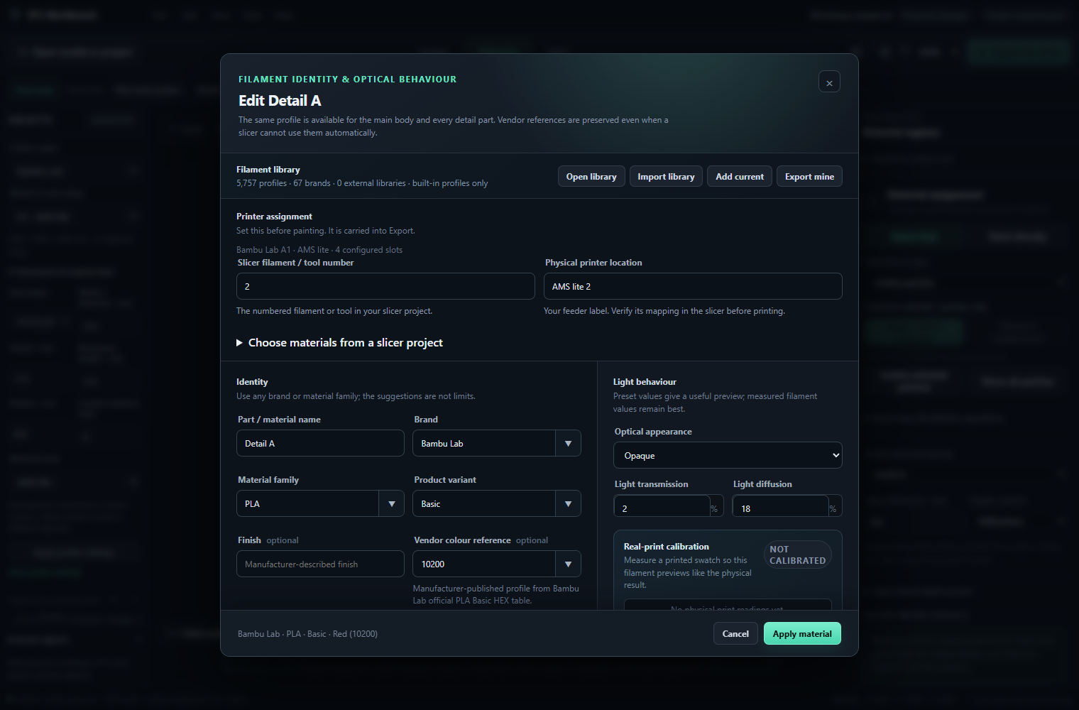
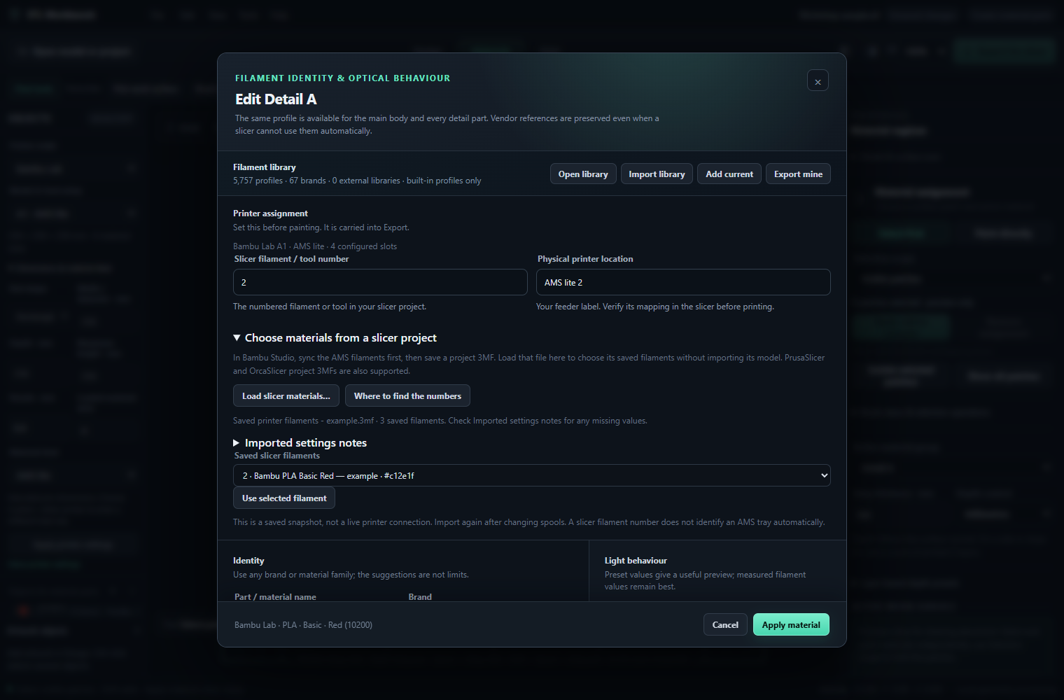
At the top of Material profile, Printer assignment separates the slicer's numbered filament from the spool's physical position:
| Field | Meaning |
|---|---|
| Slicer filament / tool number | A whole number from 1 to 64 identifying the intended filament or tool in the slicer project; Apply material carries it into export mapping |
| Physical printer location | Your descriptive feeder label, such as AMS A1, AMS lite 2, MMU 3, Tool 2 or External spool; it does not automatically remap a physical feeder |
For example, a red Workbench detail may use slicer filament 2 while its actual spool is in a tray named AMS A1. Those labels can differ. Verify the slicer's final tray/tool mapping against the loaded printer. Apply material commits both fields to the project; an MDP preserves them. The export dialog still lets you review or revise numbered mapping before writing the 3MF.
Detect printers and read their material feeders
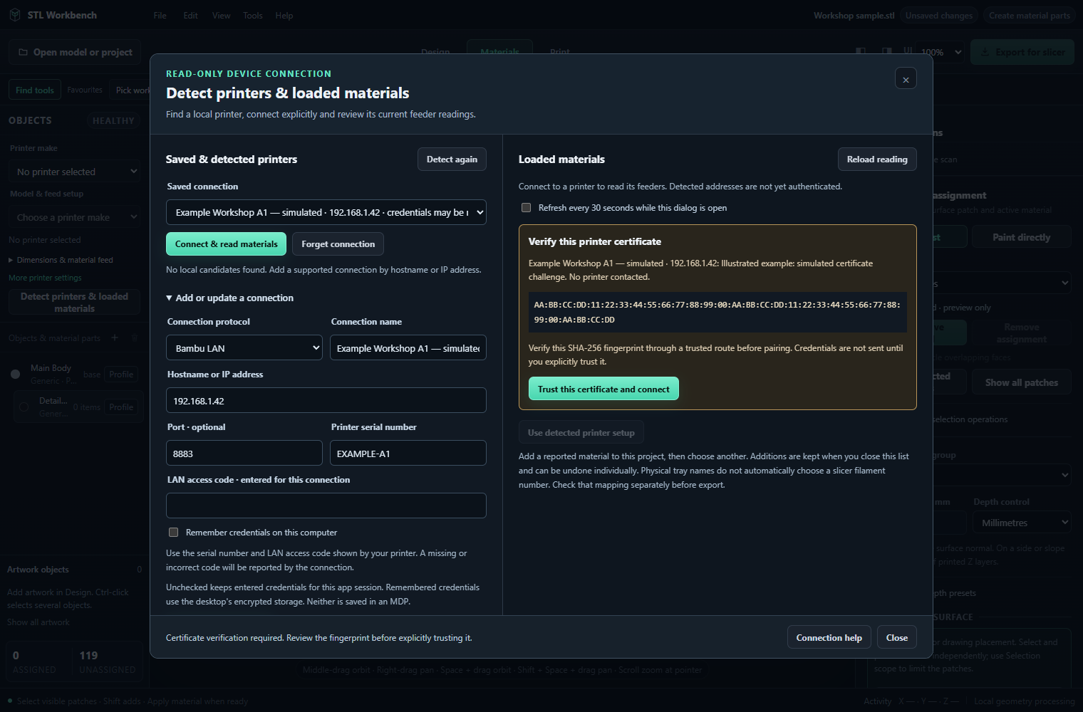
In the Windows desktop edition, choose Detect printers & loaded materials below Printer setup or inside Material profile → Printer assignment. The dialog separates discovered addresses, saved connections and current readings. A discovered candidate is not connected until Connect & read materials succeeds. Choose Use this address, or expand Add or update a connection to enter a local hostname/IP address manually. This release supports Bambu LAN, Moonraker and PrusaLink connection protocols; other discovered devices do not gain a working adapter automatically.
- Choose the correct protocol and enter a connection name and local hostname/IP. Enter a port only when the printer uses a non-default port. Use a hostname or IP, not a complete URL.
- For Bambu LAN, enter the printer serial number and LAN access code shown by the printer. For Moonraker or PrusaLink, enter an API key if that server requires one. Use Save & read materials. Missing authentication or unreachable devices produce a connection message instead of a fabricated inventory.
- A Bambu certificate pairing challenge displays the host and SHA-256 fingerprint. Verify the fingerprint through a trusted route before choosing Trust this certificate and connect. A changed certificate requires verification again. The access code is not sent before this explicit certificate trust step.
- Remember credentials on this computer is initially unchecked. Entered credentials then last for the app session. Remembering them uses the desktop's encrypted credential storage when available. Connection preferences stay on this computer; passwords, access codes and API keys are never saved in an editable MDP. Forget connection removes that connection and its retained credentials.
Review a reading before using it
| Display | Meaning |
|---|---|
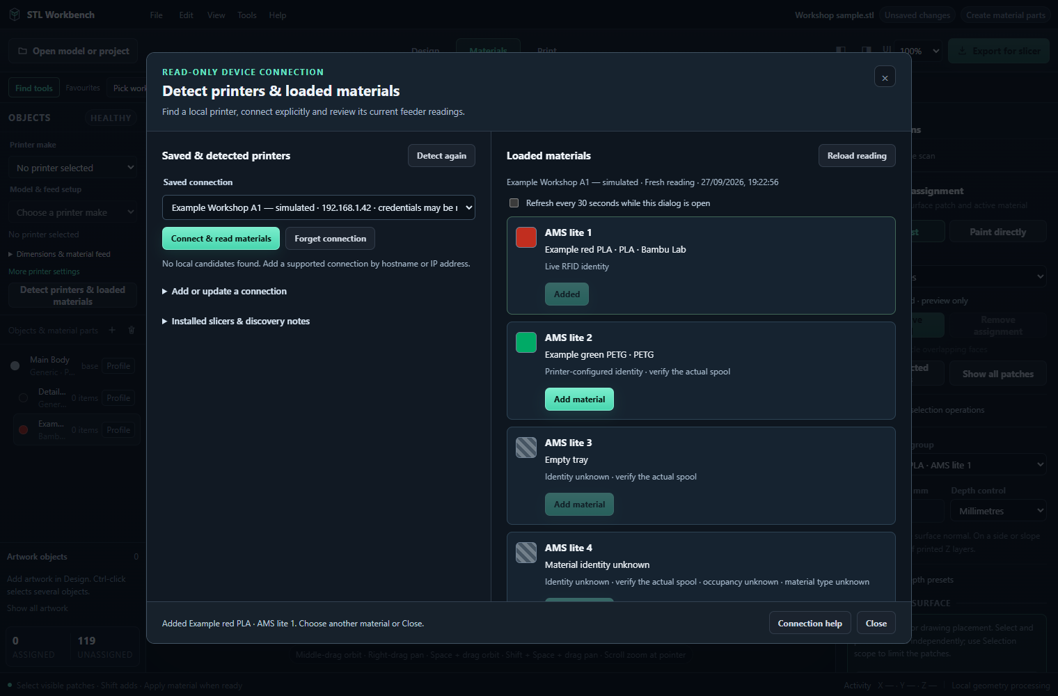
| Fresh reading and timestamp | This connection returned current information; the reading expires for material use after two minutes |
| Live RFID identity | The printer reported RFID-derived identity; review the actual spool and any reading notes |
| Printer-configured identity | A label/type/colour configured in printer software, rather than verified physical spool identity |
| Identity or occupancy unknown | The device did not establish that value; it stays unknown |
| Empty tray | Reported empty; Add material and Use in this profile are disabled |
| Cached / stale reading | Previous information shown for reference; read again before using it |
Add material beside a usable slot creates a project material immediately and keeps the list open. Add each reported material you want, then Close; the additions stay in the project. Each addition has its own Undo entry. If material parts were already built, create them again before export. Added means that this connection, slot and reported material identity already match a material in the current project. Refreshing or reopening keeps that indication; undoing or removing the material makes it available to add again. A changed spool identity can be added as a new material after Reload reading.
Adding requires an open model, a fresh reading and a non-empty slot with a reported material type or valid colour. A colour-only reading creates a material whose type is Unknown; edit its profile to enter the actual type. A name or manufacturer alone does not establish a usable material reading. Review each new material's identity, colour and depth before assigning it to the model. Its Physical printer location records the reported tray. A new material receives the next unused Slicer filament / tool number, independently of the physical tray number. Check that mapping separately before export.
When this list was opened from an existing Material profile, a secondary Use in this profile button fills that cancellable draft instead. It preserves the profile's existing slicer number. Review the fields, then Apply material to commit the draft. This secondary action is absent when opening the list below Printer setup.
Use Reload reading after changing spools. Optional Refresh every 30 seconds while this dialog is open stops when the dialog closes. Use detected printer setup is a separate explicit action available only when the reported printer model matches a verified preset; an unknown model still needs manual setup.
Adapter capabilities differ. Bambu reports supported AMS/external-spool information; configured external-spool metadata does not verify physical presence. Moonraker with Spoolman can report its configured active spool, not every loaded feeder or physical spool presence. The supported PrusaLink API reports identity and status but does not expose loaded filament brands, colours or physical slot inventory. A successful connection can therefore return no supported material slots; use manual material entry or the saved slicer-project shortcut below. Reading a printer does not upload a model, start a print or synchronize the slicer's filament list. A material with no reported colour receives a neutral preview colour with an explanation; choose its actual colour before applying it.
Choose from saved slicer filaments
Expand Choose materials from a slicer project, then choose Load slicer materials… and a saved Bambu Studio, OrcaSlicer or PrusaSlicer project 3MF. This reads its filament settings without loading its geometry. Select an entry in Saved slicer filaments and use Use selected filament to fill the material form and its slicer number. Review the imported identity, colour and missing-value notes; enter the actual physical location, which is cleared when choosing a different filament, then Apply material.
The loaded list is a saved snapshot, not a live printer connection or proof of what is currently in an AMS/MMU. Save and import a newer slicer project after changing spools. Unknown information remains unknown; saved display transparency is not a measured filament optical calibration. Where to find the numbers opens this manual's assignment guidance. Chapter 45 gives the preparation steps in the slicer.
Record a measured print
- Print a flat swatch with known layers and layer height. Enter Layers and Layer height, then confirm Thickness against the physical print. Four layers at 0.20 mm imply 0.80 mm before measurement variation.
- Enter observed Transmission, Diffusion, lighting condition and colour. Use consistent lighting when comparing thicknesses.
- Optionally load a photograph and click a representative area in the preview. Sampling averages nearby pixels; a photograph supplies colour, not a direct transmission measurement.
- Add the reading. Repeat at another thickness to improve the fitted attenuation estimate. Review the fit summary and your notes.
- Save the material. Clear readings only when you intentionally want to remove that material's recorded calibration.
17. Manual supports
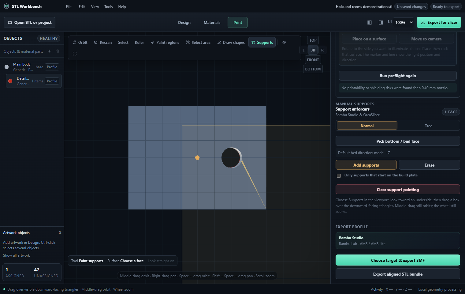
Generate the assembly before painting supports. Choose Supports, inspect an underside and drag over downward-facing triangles to add or erase support intent.
Choose whether supports must start on the build plate and confirm the intended bed direction. Clear support painting removes the manual support intent.
Export support transfer depends on the selected slicer adapter. Read the export instructions and acknowledgement. Inspect the imported support settings in the slicer; an exported annotation does not itself guarantee that the slicer will generate the intended support.
Paint support intent
- Generate a current assembly and open Manual supports in Print.
- Choose Set bed face, then pick the intended bed direction. The default is model −Z; orientation choices can change the appropriate direction.
- Choose Normal or Tree, then Add supports and drag a selection box over downward-facing triangles. Orbit to inspect hidden sides.
- Use Remove supports to erase selected intent, or Clear support painting to remove all painted support faces.
- Choose Build plate only when that is the intended support origin. Review the face count and export instructions.
Support painting marks intended areas; it is not a modelled tree or a final support toolpath. Choose a slicer adapter that can transfer the appropriate data, acknowledge its instructions, then inspect the slicer's support preview before printing.
18. Exporting to a slicer
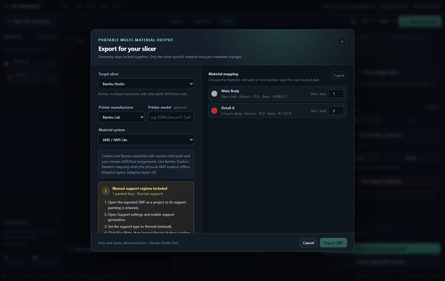
Choose Export for slicer when the material-part build is current. Select the target slicer, printer manufacturer, optional printer model and material system.
Map every locked material part to the intended filament, extruder or tool number. Review adapter compatibility notes, support instructions and the output filename, then Export 3MF.
Open the file in the chosen slicer. Confirm the shared alignment, material slots, orientation, support behaviour and adaptive-layer transfer before generating toolpaths. Keep the MDP project for future edits.
Export aligned STL bundle is the fallback when you need individual aligned mesh files. Import the bundle as one multi-part object in your slicer where appropriate. STL does not preserve the full material/project metadata of 3MF.
Export a locked assembly
- Check that the material build is current and validation is acceptable. Choose Export for slicer.
- Select Bambu Studio, PrusaSlicer, OrcaSlicer, UltiMaker Cura or Generic 3MF. Choose the printer manufacturer, optional model and material system: Automatic, AMS, MMU, Tool changer, CFS, ACE, Multiple extruders or Manual changes as applicable.
- Map every material to its intended slot/tool number. Available numeric entries do not establish the physical capacity of your printer; use its actual loaded arrangement.
- Read the compatibility note and any support acknowledgement. Confirm the part count and filename.
- Export 3MF, open it in the selected slicer as a multi-part object and check orientation, scale, alignment, colours, slots, support and adaptive layers.
- Save an MDP beside the export. For example,
panel-v03.mdpretains the editable design whilepanel-v03.3mfis its manufacturing handoff.
Export aligned STL bundle writes the separate mesh parts with shared coordinates. Keep their origin/scale when importing together. Ordinary STL has no filament slots, calibrated profile, editable artwork or undo history. Do not use an exported STL as a substitute for the MDP project.
19. Undo, issues and interface preferences
Ctrl+Z undoes document edits and Ctrl+Y redoes them. Project files include editing history. View navigation and temporary selections should not consume the document history unnecessarily.
Activity & issues keeps messages and errors after toasts disappear. Open Activity from the status bar, read the latest entries and clear them only when you no longer need them.
The panel controls show or hide Objects and the inspector. Drag a panel edge, or focus its separator and use arrow keys, to resize it. The UI selector enlarges interface text. Preferences are local to this computer.
Workspace tabs support Left/Right arrows, Home and End. Menus support arrow navigation and Escape. The instruction manual search finds chapter titles and text; press Ctrl+F while the manual is open to focus its search.
Recover and inspect a change
Use Undo after a mistaken assignment, material deletion, artwork edit, solid transform or applied model replacement. Redo restores the undone change until a new document edit creates a different history branch. Undoing an applied blank design can return to a genuinely empty model; it must be applied again before material work.
Temporary selection, isolation, camera and panel layout are inspection choices. Hide/Show is a viewport choice. Do not depend on them to remove printable geometry. Read the build-current indicator after any change that could affect export.
The Activity button opens persistent messages. Errors contain the actual import/build/export reason; review them after a toast disappears. Clear removes the message list, not the project. Instruction manual opens this searchable offline guide; select any screenshot for a larger view. Guided tutorial observes completed project steps; loading its sample replaces the current document through the normal project-change workflow.
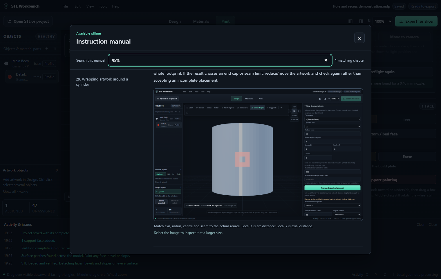
20. Choosing the right surface operation
Planar drawing uses a local plane. It does not automatically wrap text around a cylinder or maintain a constant-depth inlay over an arbitrary curved mesh.
Cylindrical wrap, directional projection and constrained conforming placement have their own checked placement operations. Open Wrap & project artwork for a selected drawing. Do not infer those operations from the ability to paint a small detected curved-surface patch.
Vector artwork and material partitioning are distinct from solid modelling. Use the Solid design section for editable bodies and holes, and apply the result to the model before continuing with surface materials.
| Intended result | Choose |
|---|---|
| Flush detail on a flat top, side, underside or angled face | A picked planar work surface and ordinary drawing |
| Flush detail following a cylinder's circumference | Cylindrical wrap with a matched axis/radius/centre |
| Artwork cast from one direction onto a gently curved region | Directional projection |
| Checked curved artwork with depth along local normals | Conform to local normals |
| Raised text, a cut pocket or a separate body | Artwork extrusion/emboss/engrave in Solid design |
| Move existing mesh vertices/features | Mesh editor / Rebuilder |
Example: put a flat logo on the side of a box by picking that side, looking at the work surface and drawing in its Local X/Y grid. A round bottle label instead needs Cylindrical wrap and a radius matching the bottle's actual mesh.
21. Troubleshooting
Cannot find drawing controls: choose Design or Draw shapes. The drawing palette should appear before paint settings. Choose a model and work surface first.
A surface cannot be selected: rotate or use a named view; check whether an active recess filter or selection scope excludes it. Clear the guide or choose the intended work surface.
No part was produced: check the active material, selected assignments, drawing footprint and depth. The artwork must intersect valid source volume.
Export is disabled or reports stale parts: create or rebuild material parts after geometry, depth or dependent settings changes. Read Activity & issues for the exact reason.
An import or build failed: keep the last valid project, review the persistent message and correct the source or settings. Save a copy before making large corrective changes.
The sliced result differs from the preview: verify dimensions, material-slot mapping, printer/nozzle limits and slicer support/adaptive settings. The slicer toolpaths are the final manufacturing preview.
| Symptom | Check and corrective action |
|---|---|
| Artwork is on the wrong side | Select the intended face, Look at work surface and confirm local axes before copying/placing |
| A number will not apply | Check units and allowed range; a box edge radius must be below half its shortest dimension and scale must be nonzero |
| Drawing cannot be moved | Check Lock, selection and curved placement. Curved artwork uses numeric local placement rather than planar drag handles |
| Missing object in view | Show all artwork / Show all solids, clear patch isolation, then Fit view |
| Old model remains after Apply fails | Read the geometry error and correct the editable scene; the last valid model is retained |
| Curved artwork needs checking again | Source geometry changed; explicitly Preview & apply placement against the current source |
| Two materials overlap | Move/resize the footprints or reduce depth, then rebuild; the error reports affected material names and overlap volume |
| Rebuilder return is rejected | Workbench changed while the editor was open. Save the editor's MDP to keep its edits, then resolve which document should be used |
| Save completes but still says Unsaved | A newer revision was edited during the save; save the current revision again |
After a failure, preserve a project copy and copy the persistent message with the triggering steps. A screenshot of the assembled colour alone may hide a thickness or solid-topology problem.
22. Keyboard reference
Desktop File shortcuts are Ctrl+O for open STL/project, Ctrl+Shift+O for open project, Ctrl+S for save, Ctrl+Alt+S for save as and Ctrl+Shift+S for export for slicer. Browser Save uses Ctrl+S/Ctrl+Alt+S; use the visible File menu for opening and slicer export so browser shortcuts do not intercept the command.
Ctrl+Z: undo. Ctrl+Y: redo. F: fit model. X: X-ray. Number keys 1–5: Top, Front, Left, Right and Bottom views.
Space + left-drag: orbit from any tool. Shift + Space + left-drag: pan. These camera gestures do not apply while typing in a field or interacting with a dialog.
Escape closes menus and modal help. Editing fields keep normal text-input behavior. Menu labels display the available shortcuts; the desktop application may register them through its native menu.
| Key or gesture | Action |
|---|---|
| Copy artwork / Paste artwork and Copy solids / Paste solids buttons | Store and paste the selected document objects; text fields retain ordinary text copying |
| Ctrl-click selected object lists | Add/remove objects in a multiple selection |
| Space + left drag | Orbit while another tool is active |
| Shift + Space + left drag | Pan while another tool is active |
| Mouse wheel / trackpad zoom gesture | Zoom towards the pointer in the viewport |
| Left/Right, Home/End on workspace tabs | Navigate Design / Materials / Print |
| Arrow keys on focused panel separator | Resize that panel |
| Ctrl+F in the manual | Focus manual search |
| Escape in an enlarged screenshot | Close that screenshot and return to its button |
Keyboard commands apply to the active document. Typing in an input must keep ordinary text selection, editing and clipboard behaviour. Use the visible File/Edit/View menus when a platform shortcut is unavailable.
23. Managing and precisely placing artwork
Artwork objects lists individual drawings on the left. Select an object, or Ctrl-click to select several. Hide affects its visibility; Lock prevents geometry edits. Only isolates one drawing; Show all artwork restores the full view.
Hiding changes the viewport, not the exported material geometry. Use Delete or remove the material assignment when you intend to remove printable artwork.
Artwork objects & placement edits a selected object's name and its Local X and Local Y coordinates in millimetres. Existing Width, Height and Rotation controls remain on the selected drawing card. Position is measured in the chosen work surface's local axes.
Group is an artwork-selection group, separate from its material group. Grouped drawings still retain individual editable shapes and material assignments. Ungroup separates the selection group. Duplicate and Delete apply to editable selected drawings.
Copy artwork and Paste artwork use the artwork clipboard. Copy a selection with the visible button before pasting. Text fields retain ordinary text copy and paste; use the artwork buttons for document objects.
Align, mirror & repeat aligns centres or edges, distributes three or more shapes along X or Y, mirrors artwork and creates arrays with a count and local X/Y spacing. Alignment and distribution require compatible work surfaces. Copy to surface places copies on a saved work surface; review their local placement afterward.
Ruler starts a two-point measurement on the model. Inspect the measured distance and use numeric placement controls for exact edits.
Position several objects
- Select one artwork entry, or Ctrl-click several compatible entries. Check which objects are locked.
- Enter Local X / Local Y in millimetres, then Width, Height and Rotation for precise individual placement. A 10 mm Local X movement follows the picked face's local X arrow, including on an angled face.
- Choose an alignment target: horizontal/vertical centres or left/right/top/bottom edges. Alignment uses the selected artwork's local bounds.
- Distribute X or Y when at least three compatible drawings are selected. Mirror X/Y reflects artwork in its work-surface coordinates; inspect text readability afterward.
- For a repeated row, use Count 4, X spacing 12 mm, Y spacing 0 mm and Create pattern. Inspect the four placements and adjust spacing to avoid overlap.
- Copy to surface requires a saved destination work surface. Review the copied artwork's orientation and Local X/Y on that surface before building.
Use Group for artwork you want to select together, such as a label made from separate symbols. It does not merge their materials or make a Boolean solid group. Copy/Paste retains an independent stored selection; changing or deleting the source afterward does not intentionally change the clipboard copies.
24. SVG, image references and editable outlines
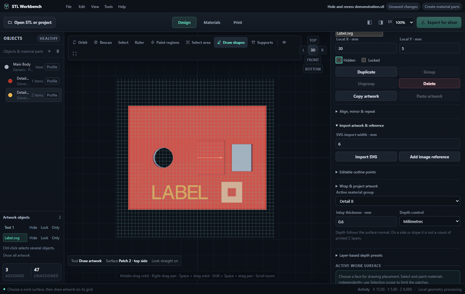
Import artwork & reference imports filled SVG paths, including holes, at the specified width in millimetres. Choose a work surface first. SVG text must be converted to outlines. Scripts, images, external resources, DTD declarations, clipping, masks and filters are rejected explicitly; strokes are ignored with a warning. Review the imported geometry and final size.
Add image reference places a local image for design guidance. Reference opacity changes its preview. Trace image outline derives artwork from the image; inspect and edit the resulting outline instead of assuming it matches every pixel. Remove reference removes the guide image.
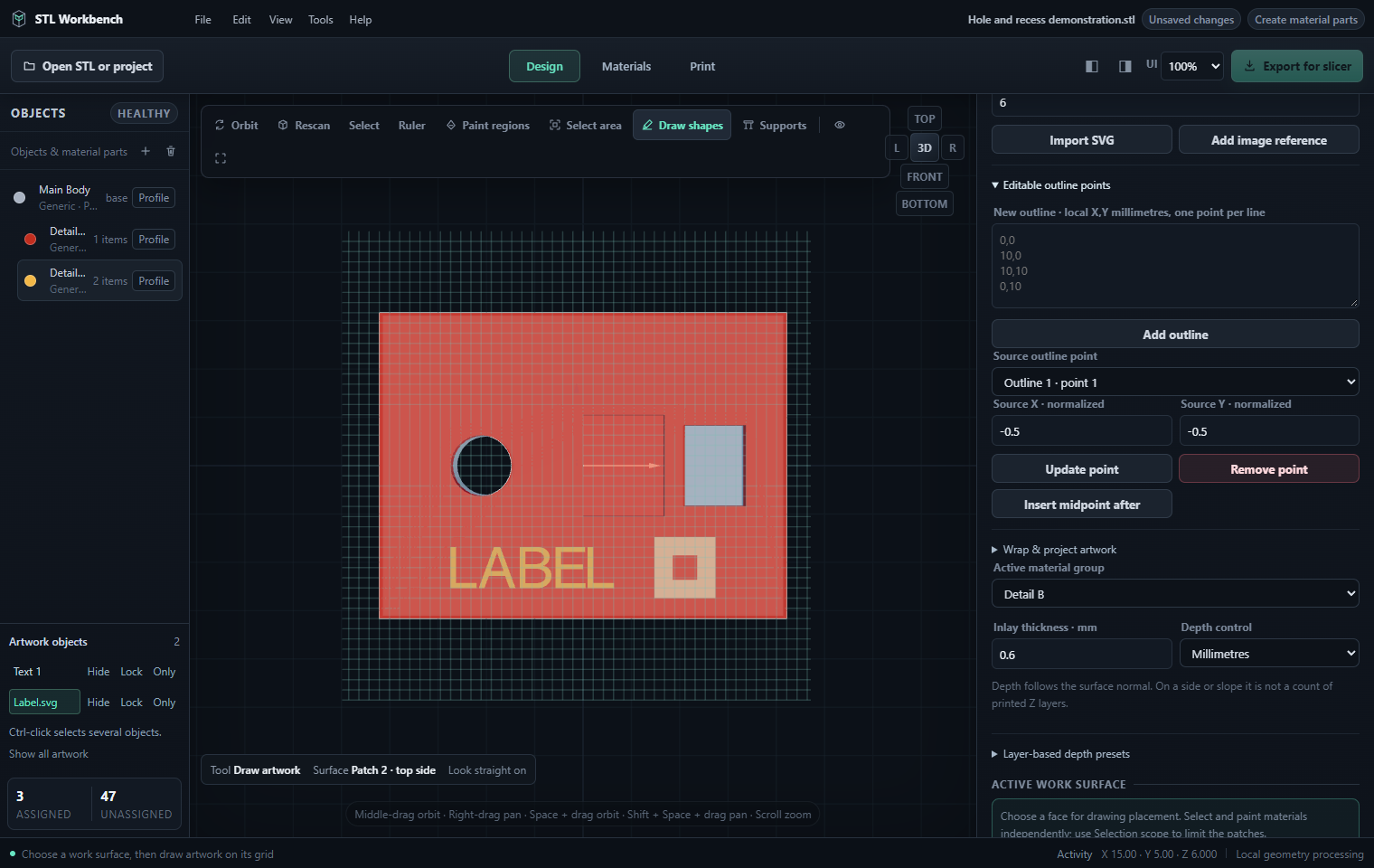
Editable outline points can create a polygon from at least three local X,Y points, entered one per line in millimetres. The point editor modifies an imported/path object's normalized source outline. Those Source X and Source Y values are scaled by the drawing's width and height; they are not millimetres. Select the intended outer-ring or hole point before updating or removing it.
Insert midpoint after adds a point halfway along the following edge. Update point moves the selected node to its entered source coordinates. Node edits preserve other rotated or mirrored points and reject crossed, degenerate or invalid hole contours.
Import a logo
- Pick the work surface and choose Import artwork & reference.
- Enter the intended SVG width, for example 30 mm, then choose a local SVG. Its filled path proportions determine the corresponding height.
- Review warnings, including ignored strokes. Convert text/strokes to filled outlines in the authoring application when their shape must be printed.
- Select the imported artwork and confirm size, holes, material and placement. Assign its depth, then build and inspect the result.
Use a photograph or edit a contour
Choose Add image reference for a local PNG, JPEG or WebP. Lower Reference opacity when it obscures the surface. Trace image outline creates editable artwork from the image, while the reference remains a visual guide; examine holes and fine detail before printing.
For a polygon, enter at least three local millimetre pairs, for example 0,0, 20,0, 10,10, one per line, and Add outline. For an existing SVG/path, select the exact outer-ring or hole node, edit Source X / Source Y, then Update point. These normalized source values preserve drawing scale; use Local X/Y or Width/Height for physical placement and dimensions.
Remove point must leave a valid contour. Insert midpoint after refines the selected edge without changing its original line shape. If an edit creates a crossing or invalid hole, the operation reports the issue and retains the previous valid outline.
25. Starting a blank solid design
Choose New blank design on the start screen or in Design. Add a Box, Cylinder or Sphere from the primitive palette. Add STL body imports another mesh into the editable scene.
Design objects lists the scene bodies and Boolean groups. Ctrl-click selects several objects. Selecting a solid opens its properties. The solid section collapses while drawing artwork so the drawing palette stays accessible.
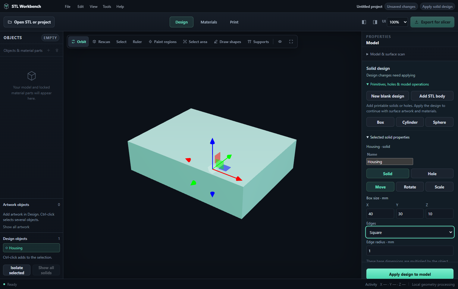
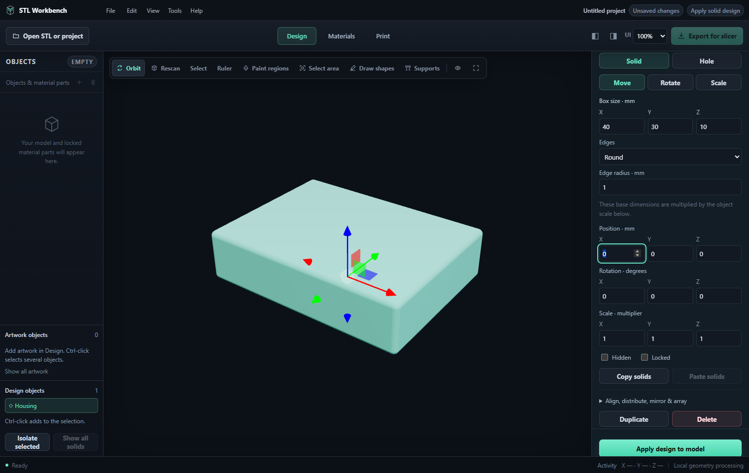
Edit a box's X/Y/Z dimensions, a cylinder's radius/height or a sphere's radius in millimetres. These base dimensions are multiplied by the object scale. Edit Name, Position in millimetres, Rotation in degrees and Scale as a multiplier. Scale values must be nonzero; a negative scale retains a mirrored axis. For example, a default 20 × 20 × 10 mm box scaled to 2, 1, 1 becomes 40 × 20 × 10 mm. Hidden controls viewport visibility and Lock protects the object's geometry from editing.
Move, Rotate and Scale select the canvas gizmo for one unlocked root object. Drag its axis handles for direct manipulation, or use the numeric fields for exact values. Select a group to transform the group; child geometry remains editable through its properties.
For a box, Edges chooses Square, Round or Bevel. Set Edge radius in millimetres. It must be smaller than half the shortest box dimension. Apply design to model evaluates the finished geometry; rounding and bevels retain the requested outer box dimensions.
Design changes need applying means the editable scene has changed since its model result was evaluated. Apply design to model evaluates it and makes the result available for work surfaces, materials and print preparation. Keep the editable MDP project so the source bodies and operation structure can be restored.
Make a simple enclosure blank
- Choose New blank design, then Box. Name it Housing and enter 40 × 30 × 10 mm.
- Enter its Position and Rotation deliberately. New primitives start with their origin at the centre of their bottom: a box at Z=0 extends upward by its height. Position moves that origin in world coordinates.
- Choose Square, Round or Bevel edges. For this 10 mm-thick box, a 1 mm edge radius is valid while 5 mm is at the prohibited half-dimension boundary.
- Use Move/Rotate/Scale handles for visual placement, then the numeric fields for exact values. A scale of 1 is unchanged, 2 doubles that axis and −1 reflects it.
- Apply design to model, inspect dimensions, then pick a work surface to add material artwork.
Add STL body places imported indexed mesh geometry into the scene; it does not infer editable CAD dimensions from the mesh. Keep the scene/MDP when primitive parameters and operation groups need to remain editable. Hidden affects inspection only; Lock prevents geometry editing and is independent from visibility.
26. Solids, holes and Boolean operations
A Solid adds printable volume. A Hole defines subtractive volume when objects are combined; a hole alone is not a printable part.
Select two or more compatible objects. Combine unites solids and uses hole objects to remove volume. Subtract removes the designated cutter volume. Intersect keeps the volume shared by the selected objects. Review the operation order and geometry result, especially when both solids and holes are selected.
The resulting group retains its editable child objects. Ungroup exposes them for further changes. Duplicate copies editable selections; Delete removes them. Copy solids stores selected bodies and their nested operation structure in the solid clipboard. Paste solids adds independent, unlocked copies to the scene. Select the copied group to move its children together.
Align, distribute, mirror & array works in world X, Y or Z using top-level object/group bounds. Align selected objects matches centres, minimum edges or maximum edges. Distribution needs three or more objects and can use equal centre spacing or equal gaps between edges. Mirror reflects the selected assembly around the centre of its combined bounds, retaining grouped holes and child transforms.
Create grid array uses per-axis instance counts and spacing in millimetres. The X × Y × Z count must total 2–200 instances, including the originals. For example, counts 2, 2, 1 produce four placements of each selected root. Isolate selected temporarily shows selected root objects; selecting a child isolates its whole root group. Show all solids restores the complete view. Isolation does not change document geometry or its build state.
Evaluation must produce valid geometry before Apply design to model commits a replacement. If evaluation fails, review Activity & issues and correct the scene; keep the last valid model. Applying new source geometry can affect surface-bound artwork and assignments, so inspect any unresolved references before rebuilding material parts.
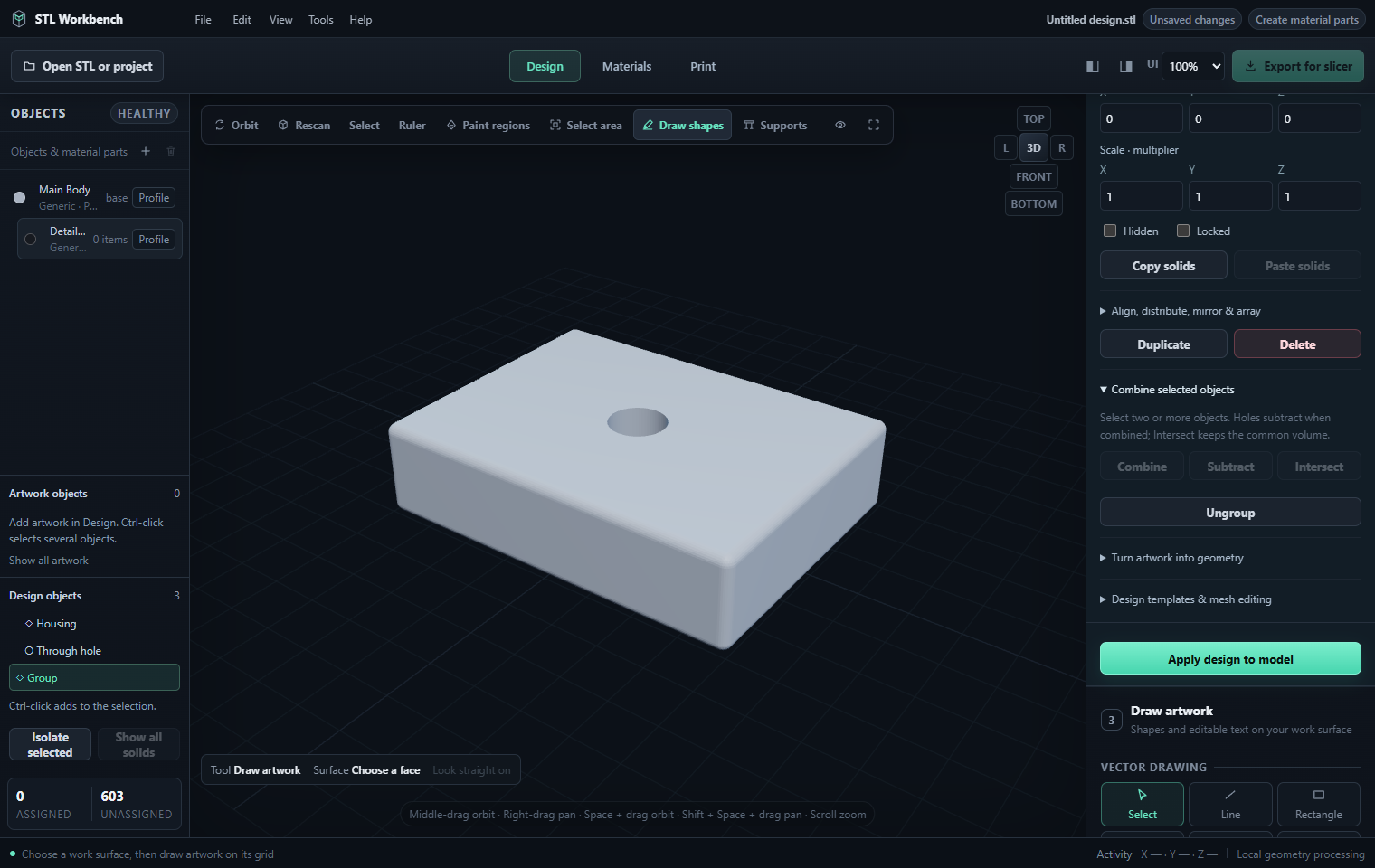
Cut a cylindrical hole
- Add a box and a cylinder. Give the cylinder a radius of 3 mm and enough height to pass through the box, for example 20 mm for a 10 mm-thick box.
- Position it inside the desired hole location and set its role to Hole.
- Select both root objects, then Combine. The group preserves the cylinder as an editable subtractive child.
- Apply design and inspect the hole from both sides. Select the group to move the entire result; select the cylinder child to change the hole geometry.
Subtract uses the operation's ordered solid/cutter relationship; select and inspect the resulting group rather than assuming selection order from the screen's visual arrangement. Intersect is useful for retaining only a common overlap. An ungrouped hole has no standalone printable volume, so apply it in a meaningful group.
Copy solids records selected roots, meshes, parameters, nested operations and transforms. Paste adds new IDs and unlocked copies, including into a different blank scene; it does not reference later source edits. Duplicate creates an immediate copy in the current scene. Ungroup preserves children in their world placement, including transformations inherited from their former group.
For a 2 × 2 grid of housings, choose counts X 2, Y 2, Z 1 and spacing larger than the housing's corresponding outer dimensions. Arrays include the original placement in their count. Alignment/distribution uses root bounds; child objects remain controlled by their parent group.
27. Extruding, embossing and engraving artwork
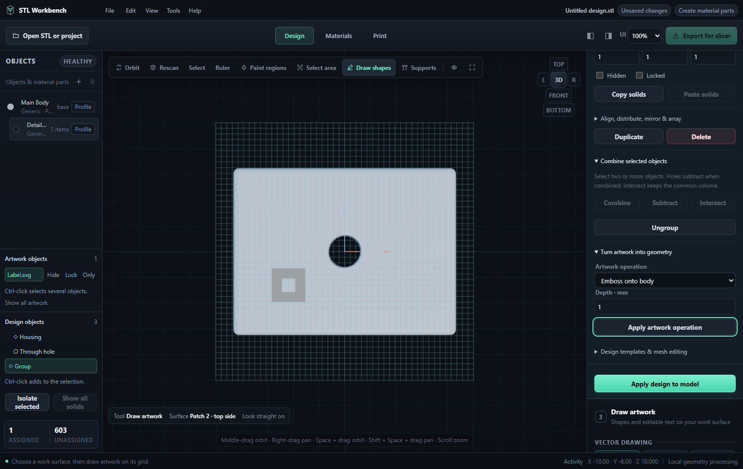
Select one or more artwork objects, then open Turn artwork into geometry. Extrude as solid creates volume from the drawing footprint. Emboss onto body adds raised volume; Engrave into body removes volume.
Set Depth in millimetres and Apply artwork operation. The operation follows the artwork's work-surface direction. Verify the result and Apply design to model as needed before assigning materials to its new faces.
Flush material artwork remains a separate operation that partitions the existing exterior. Use emboss or engrave only when you intend to change the exterior geometry.
Turn a label into a raised or cut feature
- Place and select artwork on a work surface. Verify its text/outline and physical size first.
- Choose Extrude as solid, Emboss onto body or Engrave into body in Turn artwork into geometry.
- Enter a positive depth, such as 1 mm, then Apply artwork operation.
- Inspect the new solid structure/result, apply design to the model and inspect the surface from a side view.
- Re-select appropriate current surfaces before assigning material parts to the changed body.
Extrude creates a body from the footprint. Emboss adds an exterior feature; engrave cuts into existing volume. A 1 mm engraved label should remove 1 mm along the artwork's checked work-surface direction, subject to valid intersections. These operations change shape, whereas a flush coloured inlay partitions the existing exterior.
28. Templates and mesh editing
Save design template stores the editable solid scene for reuse. Load design template restores a local template file. Review scale and transforms when combining a template with a different project.
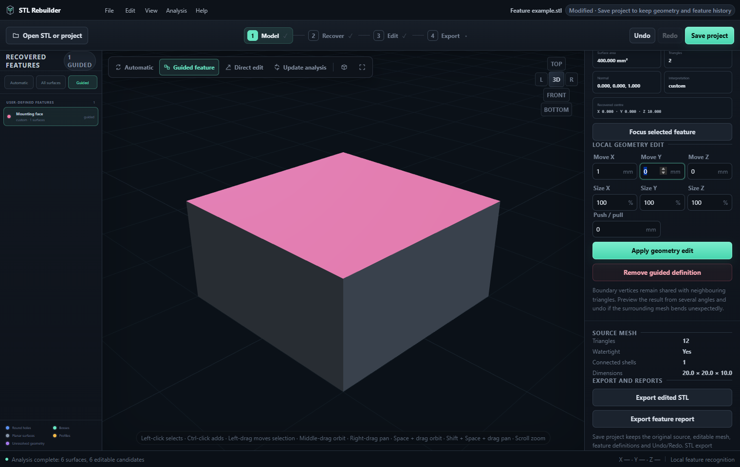
Open mesh editor opens the Rebuilder route with the current source and saved editor state. Use automatic feature recognition, guided definitions or direct mesh editing, then choose Return to Materials to apply validated edits to the original Workbench project. You can save an editable MDP from Rebuilder to preserve definitions, geometry and history without returning immediately.
Keep the original Workbench project unchanged while its mesh editor is open. Return checks its document identity and revision. If Workbench has changed, the handoff is rejected so the edited project can be saved instead of overwriting newer work.
Mesh editing moves connected source vertices; it does not recreate the original CAD feature history. Review affected neighbouring faces. A JSON recovery report describes findings; it is not the editable MDP project.
Reuse a template
Save design template writes the solid scene's editable structure to a local file. Load design template restores that scene as an undoable design change; check names, units and transforms after loading. Apply the loaded design before surface/material work.
Edit a recovered or guided mesh feature
- In Workbench choose Open mesh editor, or open an STL/MDP in the standalone Rebuilder.
- Inspect automatic findings. Automatic recognition is a candidate analysis of triangle geometry; unresolved surfaces need review.
- In Guided definitions, select appropriate surface patches, choose Hole, Pocket, Boss, Slot, Text, Tab or Custom and give the definition a meaningful name. Create guided definition stores that explicit selection.
- Select the feature and enter Move X/Y/Z in millimetres, Size X/Y/Z as percentages (100% unchanged), Push / pull as a normal offset in millimetres or Diameter when offered. Apply geometry edit changes connected source vertices.
- Inspect neighbours and undo a bad edit. Shared boundary vertices can move adjacent faces; the operation does not reconstruct original sketches or parametric CAD constraints.
- Update analysis re-examines the current edited mesh. Smooth angle (5–60°, initially 32°) and Minimum area control analysis grouping. Review measurements and any definitions requiring attention; Undo can restore the earlier analysis.
- Save editable MDP, or Return to Materials. Return waits for Workbench acceptance before closing. A revision mismatch leaves the editor available so you can save its MDP.
Remove guided definition removes that definition, not the geometry it described. Export edited STL writes the current mesh only. Export feature report writes analysis information. Save project preserves original source, edited geometry, feature definitions, analysis and history in an editable MDP for reopening.
29. Wrapping artwork around a cylinder
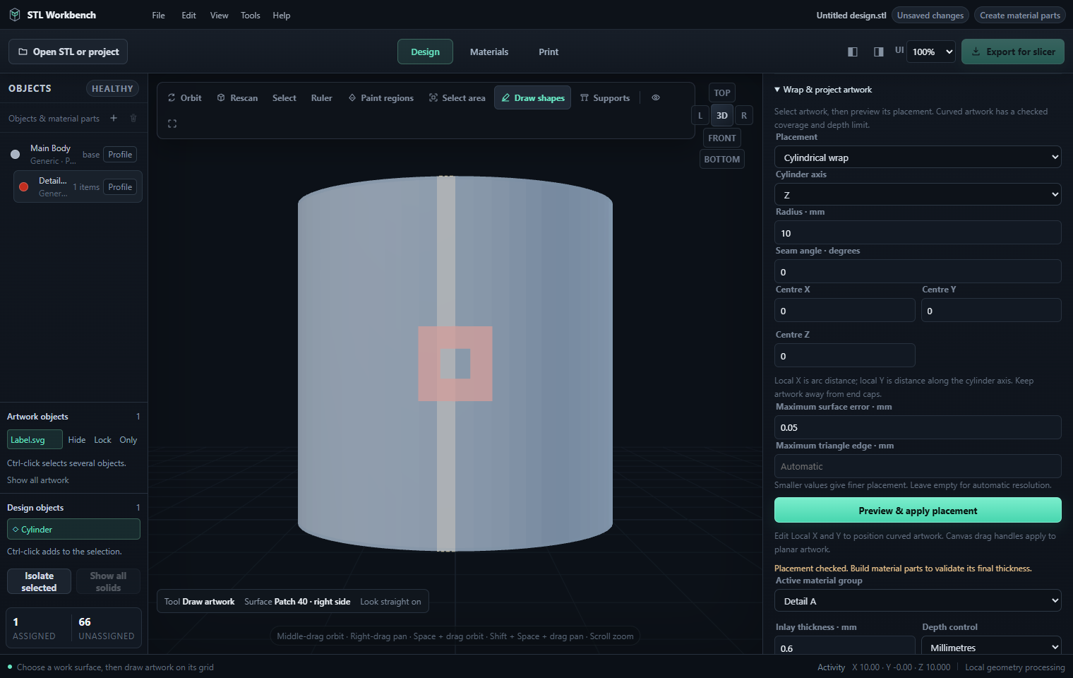
Select an artwork object and open Wrap & project artwork. Choose Cylindrical wrap, set the cylinder axis, radius and centre, then set the seam angle. Use the model dimensions and orientation to match the intended cylindrical surface.
The drawing's Local X coordinate becomes arc distance around the cylinder in millimetres. Local Y becomes axial distance from the fitted centre. The seam angle places the circumference's start direction. Keep artwork away from end caps and leave a seam gap; an artwork extent of 95% of the circumference or more is rejected.
Set Maximum surface error and, optionally, Maximum triangle edge, then Preview & apply placement. The triangle-edge value is the placement resolution in millimetres: smaller values produce a finer approximation; an empty field uses automatic resolution. The check must cover the entire artwork on a fitting surface. Create material parts to validate the final inlay. Cylindrical inlay thickness is radial into the cylinder, not measured along the printer's Z axis.
Place a cylinder label
- Apply or import a cylinder and inspect its radius, axis and centre. For a radius of 10 mm, circumference is about 62.83 mm.
- Make artwork narrower than 95% of that circumference and clear of the end caps. A 20 × 8 mm label is a more manageable first test than a nearly full-wrap label.
- Select it, choose Cylindrical wrap, set Axis Z for an upright cylinder, Radius 10 mm and the actual Centre X/Y/Z.
- Set Seam angle in degrees, then place the artwork with Local X as arc distance and Local Y as axial distance. Use numeric placement for curved artwork.
- Begin with Maximum surface error 0.05 mm and automatic Maximum triangle edge. Preview & apply, inspect all edges, then build material parts.
Smaller surface error or triangle edge can increase resolution and work. Coverage/distortion must pass over the whole footprint. If the result crosses an end cap or seam limit, reduce/move the artwork and check again rather than accepting an incomplete placement.
30. Projecting and conforming artwork
Directional projection casts artwork along the chosen work-surface normal or a named axis direction onto the first visible source surface. Its thickness is measured along that projection direction. Use it for artwork placed from a consistent viewing/placement direction; hidden or uncovered areas are not silently filled.
Conform to local normals starts with the same ray placement, then follows smoothed local normals for its thickness. This supports constrained curved regions; it does not promise arbitrary freeform wrapping across sharp edges or all scanned meshes.
Choose the placement and projection direction, set Maximum surface error and Preview & apply placement. Maximum triangle edge controls resolution in millimetres; leave it empty for automatic resolution. Inspect the checked result, then create material parts. A smaller edge or allowed error produces a finer approximation and can increase processing time.
Placement preview checks coverage and distortion. The final material Build additionally checks thickness and closed-volume safety against the source mesh, including hidden walls, underside dents and enclosed cavities. A successful placement preview alone does not prove a safe inlay depth.
Coverage gaps, grazing incidence, sharp transitions, local curvature, folding, self-intersection, insufficient wall depth and invalid solid topology stop the operation. Reduce the artwork extent or depth, choose a better direction or divide the artwork into suitable regions, then check again. Planar work surface restores ordinary planar placement.
Curved placement belongs to a particular source geometry. Rescanning the same model retains it; replacing or changing that geometry requires explicitly previewing and applying the placement again. Resolve that state before building material parts.
Project onto a shaped surface
- Place an outline where the desired projection rays cover the target. Choose Directional projection or Conform to local normals.
- Set Direction to the work-surface normal, From above (+Z), From right (+X) or From rear (+Y) according to the intended approach.
- Use the initial 0.05 mm Maximum surface error (field range 0.005–0.2 mm), with automatic triangle edge for the first test.
- Preview & apply placement. Inspect the status and full footprint from multiple angles.
- Choose a conservative material depth and Build. If hidden walls/cavities prevent safe depth, reduce depth or change the placement region/direction.
Directional projection is useful for a label seen from one approach direction. Conforming depth follows local normals and therefore has extra curvature/folding constraints. Neither mode fills uncovered parts silently. Returning to Planar work surface removes the special curved placement mode for ordinary plane-based artwork.
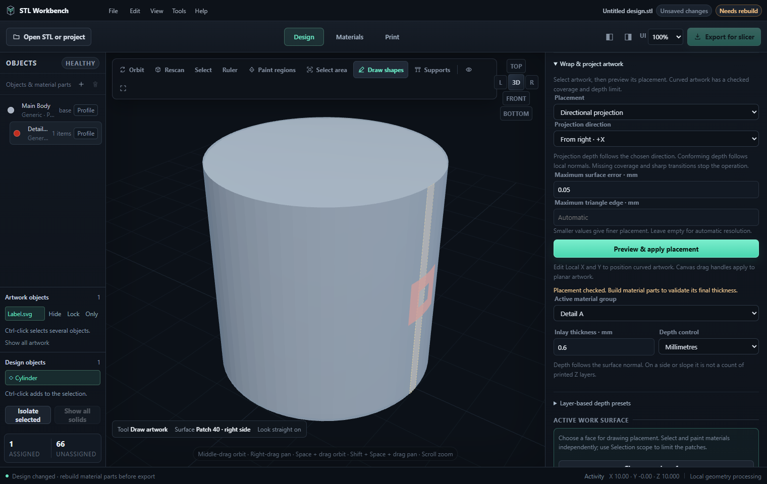
Follow a connected surface around the model
Select an unlocked artwork object and choose Follow connected surface from anchor. Click Pick surface anchor, then click the applied source model where the artwork's surface origin should lie. The displayed anchor gives its coordinates and source triangle. Anchor frame rotation turns the initial local X/Y directions in that surface.
Local X and Local Y now represent distances travelled across connected source triangles. The placement can follow the model around to rear faces or into an undercut that a single projection ray cannot reach. Adjust these values to move the artwork from its picked origin. Preview & apply placement checks its footprint; Create material parts additionally checks the real depth along the local normals. A surface origin and its source identity are saved with the artwork in the MDP.
Reduce Maximum triangle edge for a finer approximation and use Maximum surface error to set the accepted placement tolerance. Smaller values cost more processing. This is a mesh-following surface grid: large wraps, open boundaries, sharp or inverted joins, excessive distortion, intersecting offsets or insufficient wall thickness can still fail validation. Reduce the extent or depth, move the anchor, or split the artwork into smaller pieces. A changed source requires a new valid anchor; it does not silently reuse old triangle coordinates.
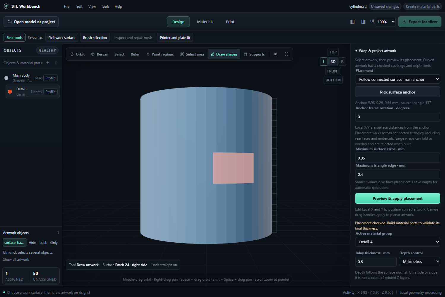
31. Material overlap and curved print checks
Curved parts preserve the source exterior by intersecting their volume with the source body. Final checks must still produce watertight, non-overlapping parts with conserved assembly volume.
Overlapping insert volume assigned to different materials is rejected with the material names and overlap volume in cubic millimetres. Adjacent parts may touch. Move the artwork, change its scope or reduce depth to remove an overlap before rebuilding.
Export records the intended depth meaning: planar surface-normal depth, cylindrical radial depth, projection-direction depth or conforming local-normal depth. Review the assembled geometry and material mapping in the slicer; these meanings do not convert side or curved inlays into literal printer Z-layer counts.
Resolve an overlap or depth error
- Read the material names and reported overlap volume in Activity.
- Isolate/inspect the affected drawings and source from more than one angle.
- Separate their footprints, reassign them consistently or reduce depth. Moving only the viewport or changing explode inspection cannot repair geometry.
- Rebuild and confirm conserved volume and watertight parts. Then inspect the slicer's sections/toolpaths.
Example: two different materials placed over the same cylindrical label area cannot both occupy the same 0.6 mm radial volume. Adjacent touching contours are allowed; overlapping solid volume is rejected. Likewise, a locally thin wall may require shallower inlay depth even when placement coverage passes.
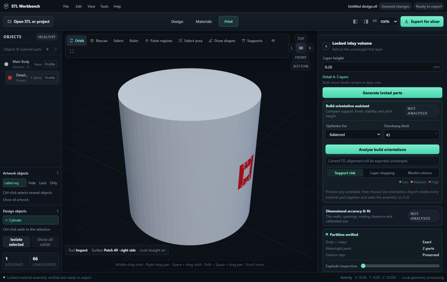
32. Desktop application and performance
Open the Windows desktop application to use native solid design. Apply design to model automatically uses the native engine when installed. Material builds default to Auto, which currently uses WebAssembly because it was faster on the tested large imported model. The local browser preview uses the compatible browser engine. Both routes keep the same editable MDP projects, artwork tools, tutorial and export formats.
Tools → Material builds offers Auto, Native C++ and WebAssembly in the desktop app. Choose Native C++ when you want material Boolean operations in a separate process that Cancel can stop immediately. It can take longer than a warm WebAssembly build on a dense imported mesh. Changing this preference does not change the project or invalidate an existing assembly.
Large meshes, many overlapping solids and very fine curved-artwork resolution can still take time. The build runs separately from the interface. Cancel stops the current build and retains the previous valid model or assembly. A failed native geometry operation reports its error; correct the geometry before trying again.
Surface hover updates only the patches under the pointer. Solid gizmos preview movement while dragging and commit the transform when released. Project compression and autosave run in a background worker, so saving large projects does not require compressing them on the canvas thread. Wait for the saved state before closing after a manual save.
Choose an engine and keep work safe
Use Tools → Material builds → Auto for the measured default. Choose Native C++ when immediate process cancellation is particularly useful, or WebAssembly to explicitly use the compatible worker route. Availability is checked by the desktop app; a present helper that reports invalid geometry is an operation error, not permission to silently accept a different result.
These are execution preferences, not different modelling features. The browser remains useful for designing, materials and export. Desktop additionally manages local file saving/recent projects, recovery, native geometry and optional Windows Explorer thumbnail registration.
For a heavy task, save a checkpoint, choose practical artwork resolution, start the build and watch progress. Cancel deliberately while available. The previous valid result stays usable; wait for completion/current-state confirmation before exporting the new revision. Save a current MDP after the result is accepted.
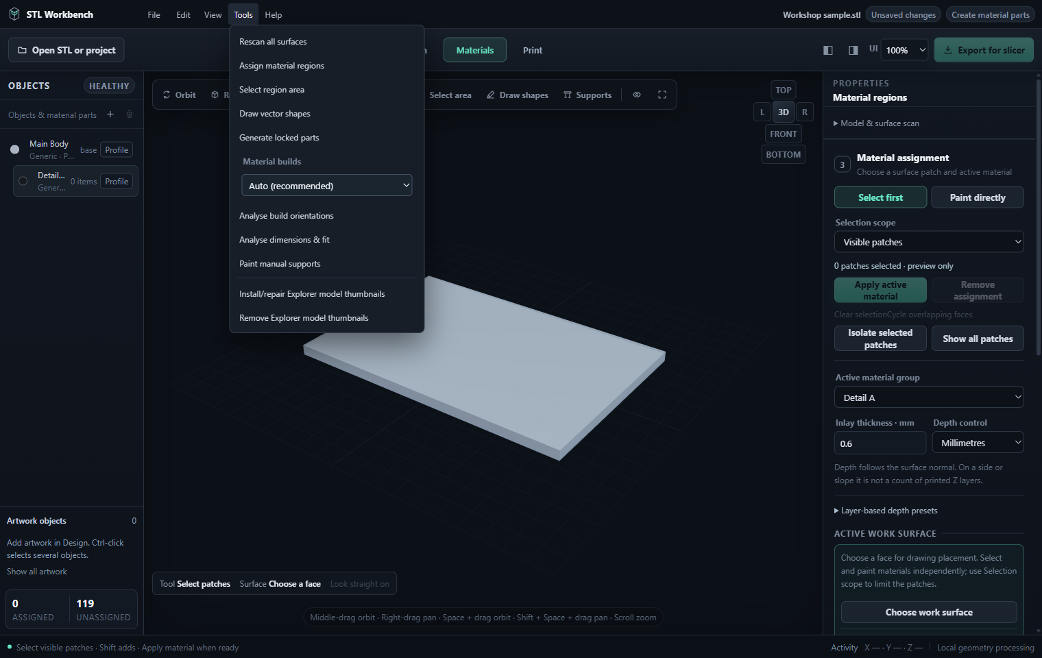
33. Read the material operation before painting
Materials now shows an operation summary beside its selection controls. Read the paint mode, selected patch count and inward depth in millimetres before Apply active material. Millimetres describe physical depth along the selected surface normal. Layer preset multiplies the material's preset by the nominal layer height; it still produces a surface-normal depth on a side or slope.
Surface patch only uses the selected surface footprint, including its holes. Use it for lettering and individual features. Fill enclosed area intentionally extends through the enclosed footprint, so its result can include the background inside a border. Choose the mode explicitly when moving between a border and lettering. The summary reports the current choice; it cannot infer what you intended to paint.
Use Select first to preview a choice and Apply active material to commit it. Remove assignment clears selected patches. Paint directly keeps the faster click-to-assign workflow. Inspect the assembled result after Create material parts, then a section or exploded view before export.
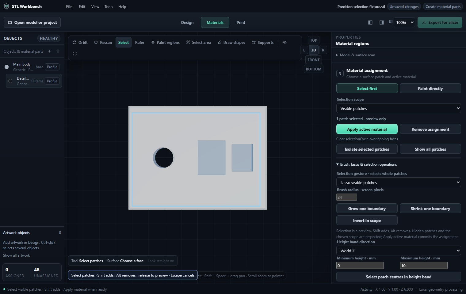
34. Brush, lasso and selection operations
Expand Brush, lasso & selection operations in Materials. Selection coverage chooses Whole detected patches or Parts of actual faces. Whole-patch mode selects detected boundaries. Partial mode clips the selected area within source triangles so a painted outline can end inside a large flat face; it creates printable material volumes when built.
- Set Selection scope. Visible patches uses the current camera and isolation; Current work surface, Coplanar patches, Matching recesses and Connected surface impose their respective geometry constraints.
- Choose Brush visible patches and set Brush radius in screen pixels, or choose Lasso visible patches and drag a closed screen outline.
- Release to inspect the highlighted selection. Shift adds to it; Alt removes from it. Escape cancels an unfinished gesture.
- Choose Apply active material only after the selection and operation summary are correct.
Grow one boundary adds adjacent allowed patches; Shrink one boundary removes boundary patches. Invert in scope selects the allowed patches outside the current selection. These operations respect the chosen scope and hidden patches. A large selection may require a short visibility check; isolate a smaller area when needed.
Grow, Shrink, Invert and height-band selection operate on whole patches and are disabled while Parts of actual faces is active.
Height band direction chooses World Z or the work-surface normal. Enter Minimum and Maximum height in millimetres, then Select patch centres in height band. The test uses patch centres, so it selects whole patches whose centres lie within the interval. It does not cut geometry at the band boundaries. Changing selection alone does not alter the assigned material.
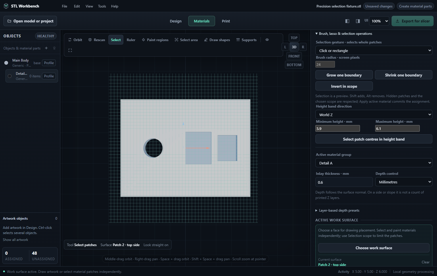
For a precise painted boundary, choose the partial-surface extent, then Brush or Lasso. Drag over the front-visible model surface, inspect the white selection and apply the active material. Hidden surface portions are excluded, including partially obscured triangles. Shift adds area and Alt subtracts it. Selection alone does not assign material. The original mesh supplies the surface: holes and empty space remain empty.
Painting the same area again replaces the earlier paint there. Erasing removes paint in the selected area; unpainted geometry and other materials outside it remain. Build uses the chosen material depth along each selected surface normal. Inspect the generated part and section before export. Save an MDP to preserve exact boundaries and Undo. If source geometry changes, old paint is marked unresolved instead of being silently projected onto a different shape.
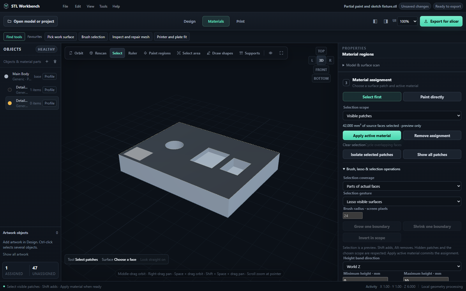
Painted face areas lists the saved assignments, their materials and areas. Remove area removes that assignment and reveals the existing whole-patch or body material underneath. Remove areas marked as belonging to an earlier source, then paint the current geometry again before building. Painting again does not resolve an old unresolved record automatically. This is different from deleting a material from the Objects panel, which offers to remove or reassign all of that material's usage.
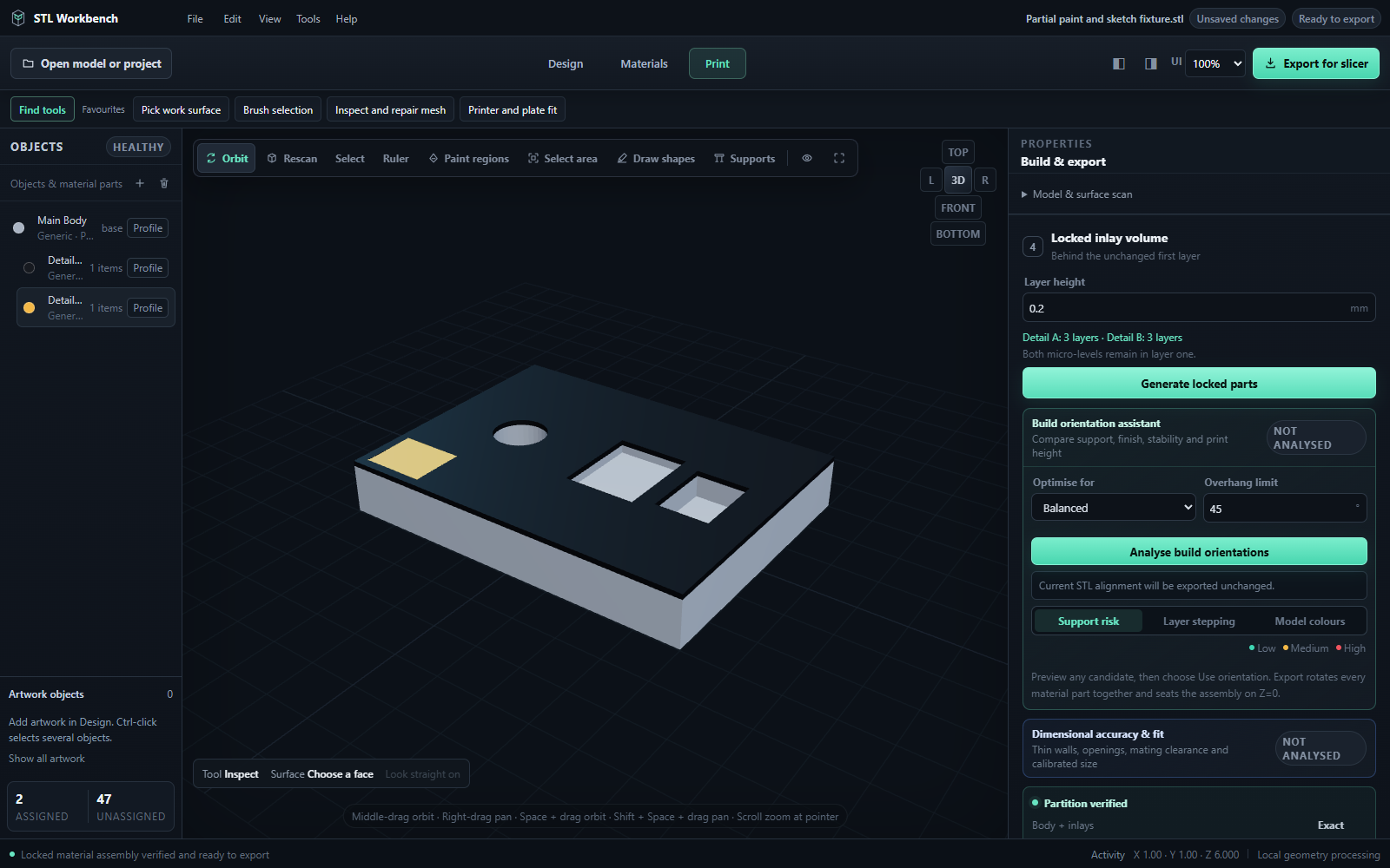
35. Geometry snapping and precision measurements
Expand Precise geometry snaps & measurements in Design. Enable Snap to vertices, boundary edges and circle centres to use detected geometry while placing planar artwork. Features must lie on the active work plane for ordinary artwork placement. Grid snapping remains available separately.
Choose a measurement, then Measure chosen geometry. Hover near a feature and inspect the snap marker before clicking.
- Point distance: choose two geometry points; the result is their three-dimensional distance in millimetres.
- Circle diameter: click near the circular boundary or its centre. The tool fits a closed tessellated boundary and reports the diameter. This is an estimate from the imported mesh's polygonal circle, with fit error when applicable.
- Angle: choose an endpoint, the angle's vertex, then the other endpoint. The result is in degrees.
- Circle centre distance: choose two fitted circle centres; the result is their three-dimensional separation in millimetres.
Use Escape to clear an incomplete picking gesture or choose another measurement to start again. Measurements are observations, not changes to the model. Zoom toward the desired feature if several nearby candidates are hard to distinguish.
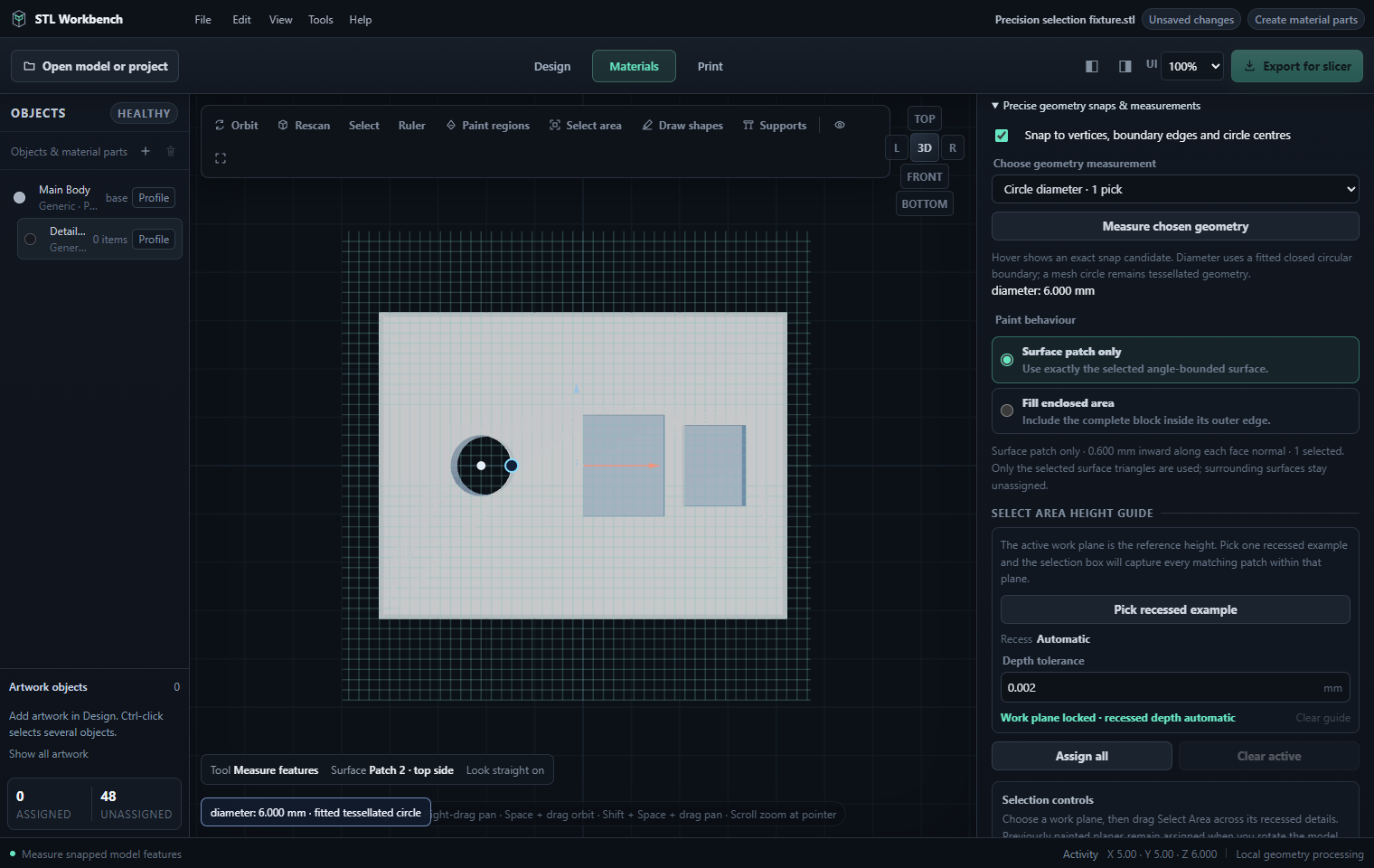
36. Drag outline nodes and curve handles
In Design, select an unlocked outline and its work surface. Expand Artwork objects & placement and the outline editor. Drag outline nodes on canvas displays nodes at their actual model positions.
Drag a node to change the outline. The canvas previews the movement; releasing validates the entire contour and records one undo step. Double-click an edge to insert a new point. Existing numeric point controls still support exact edits and removal. Escape cancels an unfinished drag.
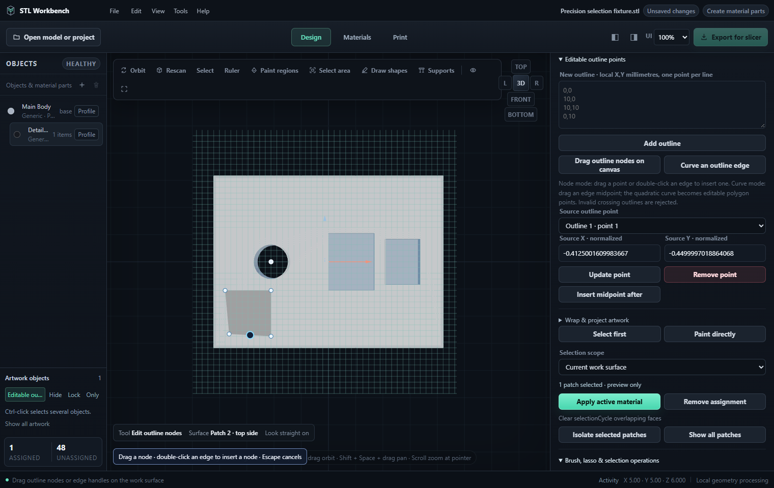
Curve an outline edge displays square midpoint handles. Drag a midpoint to bend that edge into a quadratic curve. On release the curve becomes a sequence of ordinary editable polygon points. You can edit those points afterward; this is not a persistent spline constraint. Crossed, degenerate or otherwise invalid outlines are rejected and the previous drawing remains intact.
Parametric text and shapes retain their existing editing controls until converted to a suitable editable outline. Hidden or locked artwork cannot be changed with the node tools.
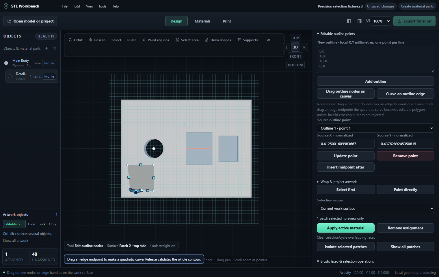
37. Align an image reference and place solids on a face
Import a reference image using the existing image controls, choose its work surface, then Align reference with two geometry points. Pick two distinct points on the displayed image, followed by the two matching target points on the model. The tool calculates a translation, rotation and uniform scale so the reference points match the geometry points. It preserves the image aspect ratio. Geometry snapping helps choose the target points accurately. Escape cancels an incomplete sequence.
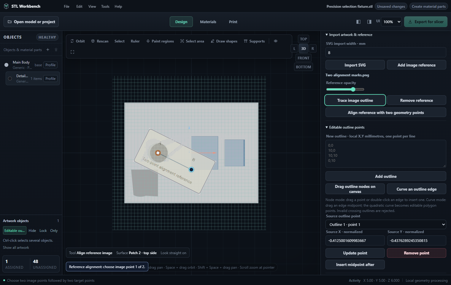
For existing solids, select unlocked top-level design bodies and expand Solid design's alignment controls. Place on picked face starts a face-picking tool on an applied model. Click the target face or a suitable snapped point. The selected assembly is oriented to the face normal and its bottom centre is moved to the picked position; its internal shape, scale and relative arrangement are preserved.
Inspect the placement from more than one direction. Face placement is an editable scene change with Undo. Apply design to model updates the source used by Materials and Print. It does not silently bake the design during the picking action. Apply a source model first if there is no face geometry to pick.
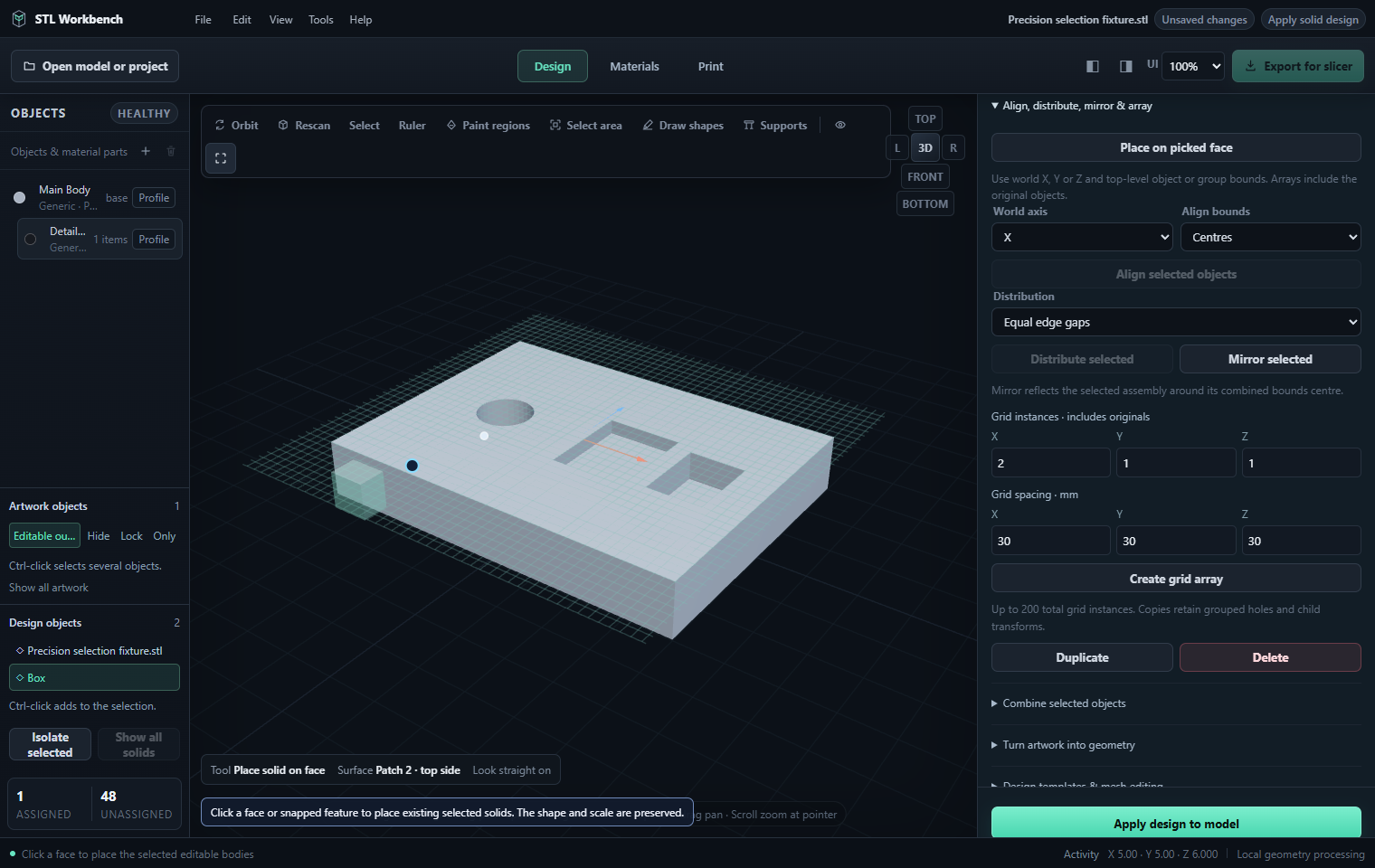
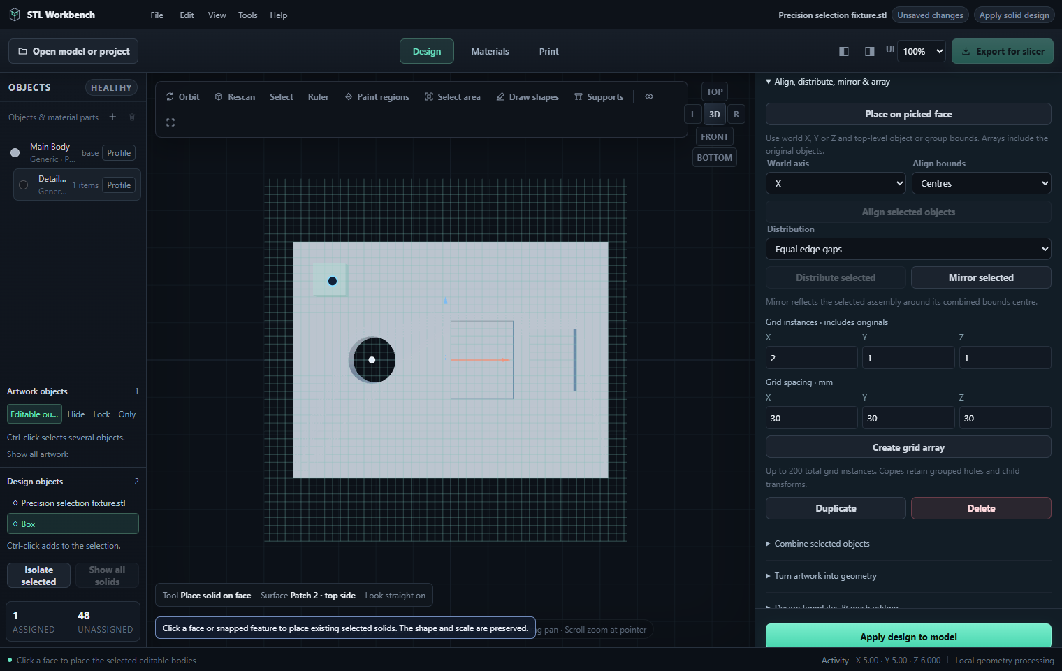
38. Mesh diagnostics and checked repair
In Design, expand Geometry tools. Select one unlocked top-level body, or use the imported source when no scene body is selected. Inspect geometry checks topology and lists connected shells, open edges, non-manifold edges, duplicate or degenerate triangles, inconsistent winding and detected self-intersections.
Choose a defect and Locate defect to focus the camera and display its red marker. Choose a shell and Isolate shell to examine just that connected component. Show all restores the inspection view. These are view actions; no triangles are removed by inspecting them. A bounded intersection scan explicitly reports incomplete analysis rather than certifying a dense mesh as safe.
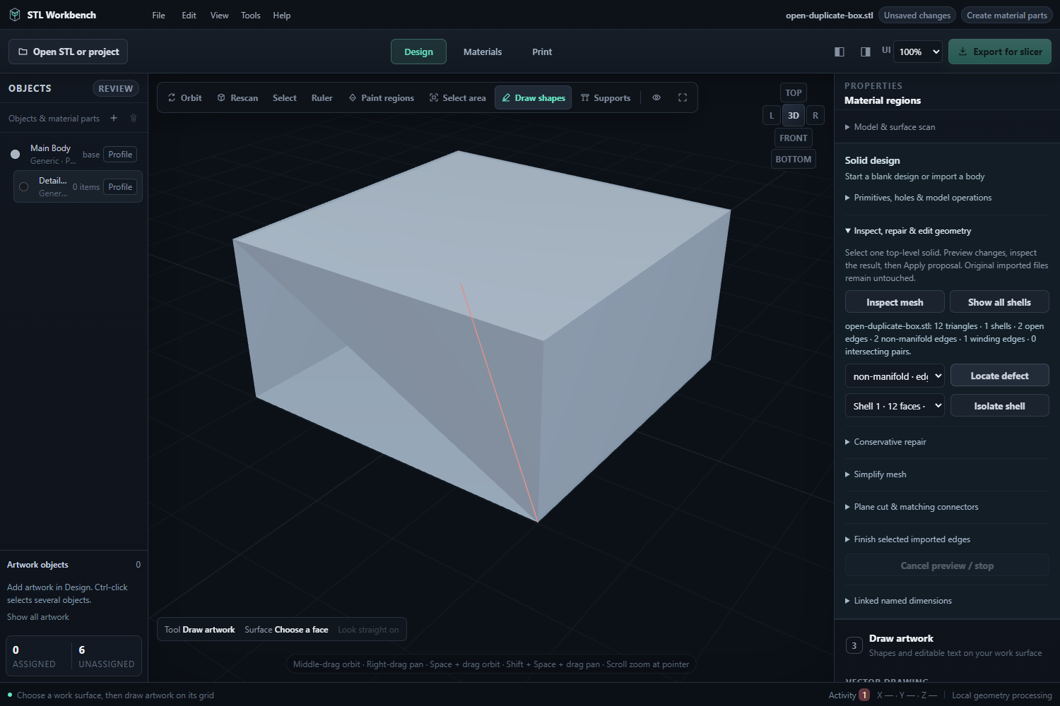
Expand Conservative repair. Set the weld tolerance in millimetres. Repair can merge coincident vertices, remove duplicate and degenerate faces and correct consistent winding. Enable planar-hole closing only when appropriate and set its maximum hole diameter. This closes small supported planar boundary loops; it cannot reconstruct arbitrary missing surfaces.
Choose Preview repair and read the before/after findings. Apply proposal accepts a verified result into the editable scene; Export proposal STL saves a separate result. Cancel preview / stop retains the original geometry. After applying, use Apply design to model to update material editing. Non-manifold structures, unresolved intersections and unsafe hole repairs remain reported failures.
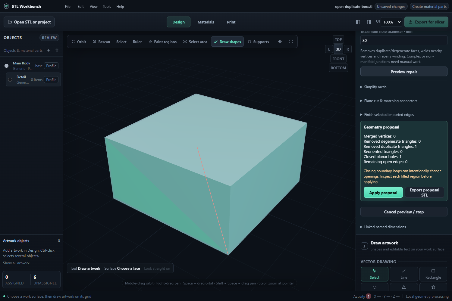
39. Simplify a mesh under a tolerance
Expand Simplify mesh inside Geometry tools. Set Tolerance in millimetres and the permitted volume change percentage, then preview. Smaller tolerances retain more detail; simple planar geometry may have nothing useful to remove.
The proposal reports original and resulting triangle counts, requested tolerance, sampled maximum surface deviation and volume change. Surface deviation is sampled in both directions; it is not a proof about every point on the surface. The operation also checks closed topology. Review thin walls, lettering and holes visually before applying a reduction.
Apply, export or cancel using the proposal controls. Apply is undoable and stores the reduced mesh as an editable body. Reapply the design and rebuild material parts afterward. The input STL is not overwritten by the preview.
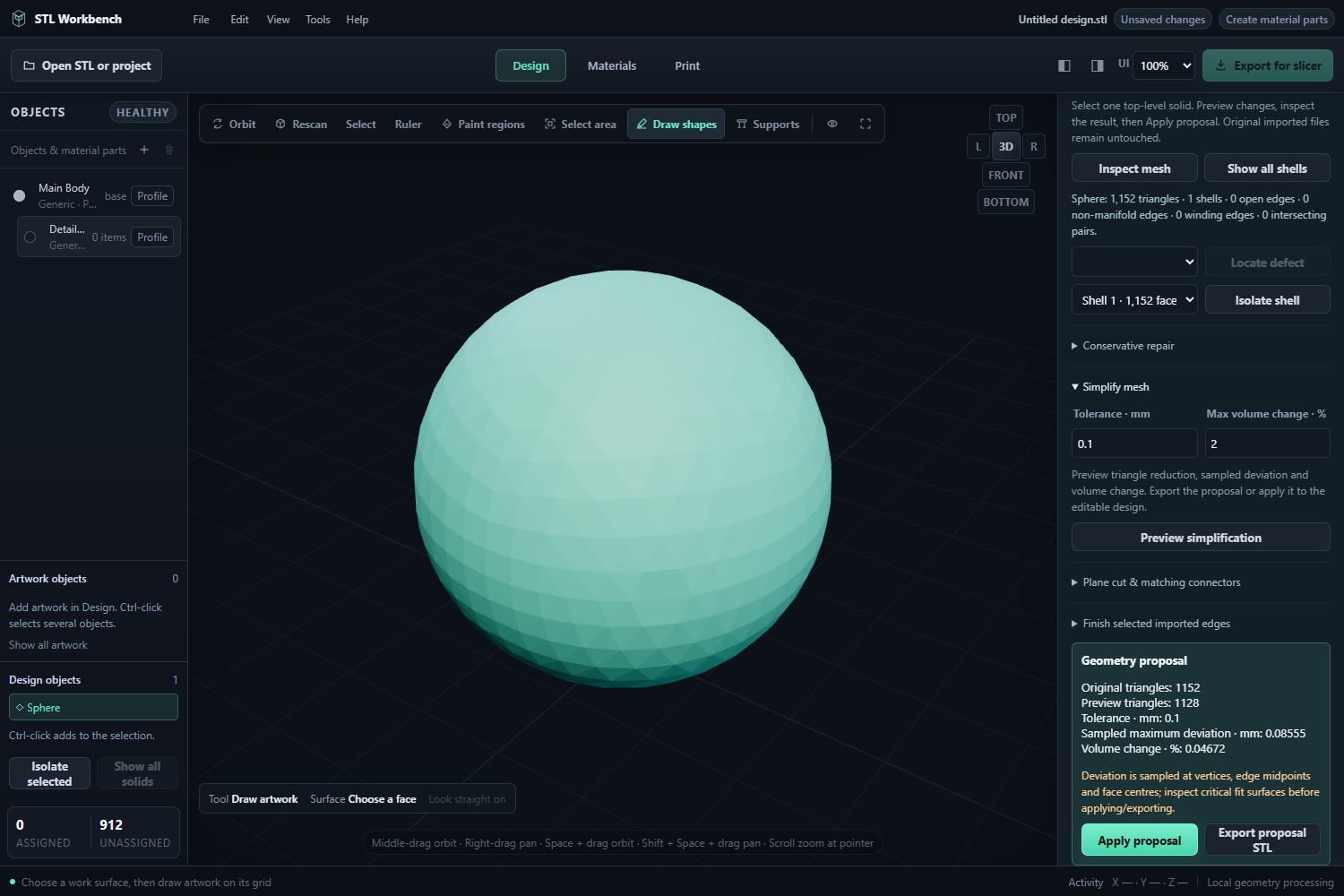
40. Plane cuts and matching connectors
Expand Plane cut & matching connectors. Enter a nonzero plane normal and its distance from the world origin in millimetres. The normal is normalized; the plane satisfies dot(position, normal) = distance. For example, normal 0,0,1 and distance 10 cuts at Z=10 mm. Choose both halves or the desired side.
Connector choices are None, Separate dowel + two sockets and Integrated plug + socket. Matching connectors require both halves. Set radius, length and radial gap, then enter one connector centre per line as world X,Y,Z coordinates lying on the cut plane. Radial gap is additional socket clearance around the connector, not a diameter value.
Preview the cut. Preview separation spreads the displayed halves so sockets and connectors can be examined. It is a view setting: exported and applied mesh coordinates remain aligned. Sockets must fit completely inside the original solid and avoid cavities, walls and other connectors. Unsupported placement stops the proposal rather than creating an unsafe connector.
Apply creates separate scene bodies; proposal export produces an STL bundle when several pieces are present. Apply design to model evaluates the resulting scene. Save an MDP to retain the editable pieces. Check a small fit sample using your actual material and printer before relying on the selected clearance.
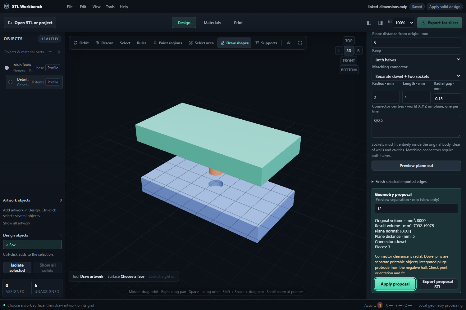
41. Finish selected imported edges
Use Inspect geometry, then expand Finish selected imported edges. The list identifies convex and concave creases with length, angle and centre coordinates. Selecting an entry marks its edge; Ctrl-click selects several. Enable connected-chain expansion to include similarly angled segments around a faceted curved rim.
Choose Bevel for a chamfer or Round for a faceted radius. Enter Size / radius in millimetres. Round segments controls the approximation resolution. Preview, inspect the affected edges and removed volume, then apply or cancel.
Convex finishes remove material; concave finishes add material inside the corner. Curved chains follow the faceted source and adjoining selected edges share a combined corner operation. The report distinguishes selected chains, curved chains, removed and added volume, and the small joint source overlap used to keep a joined result closed at STL precision. Review the exported shape as well as the preview.
The operation requires clean two-face creases and sufficient room. It protects unrelated walls and cavities, checks the result at STL import precision and rejects unsafe cuts, excessive radius or ambiguous topology. Chain expansion follows gradual turns; branching edges and sharply changing crease angles need separate selection. This is a checked mesh operation, not reconstruction of the original CAD fillet. Edit individual material bodies so their colour volumes are preserved.
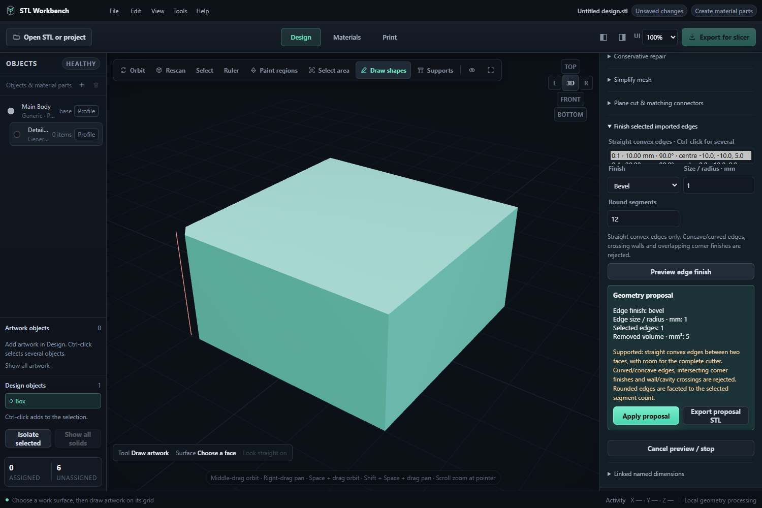
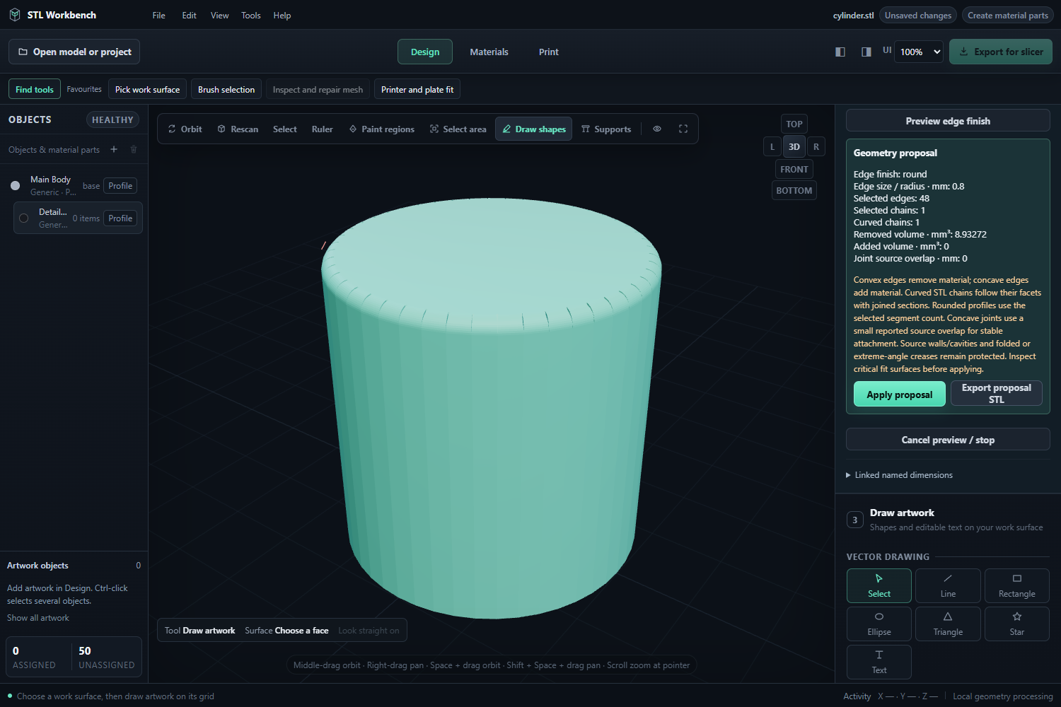
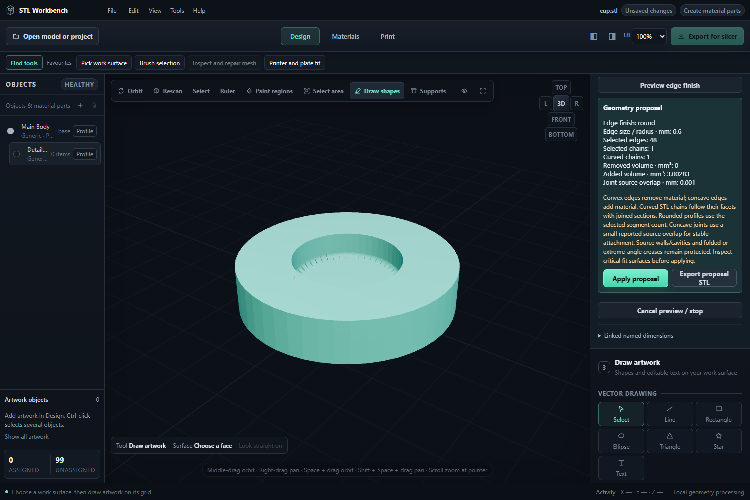
42. Link dimensions by name
Expand Linked named dimensions in Geometry tools. Enter a Dimension name and a value or expression, then Add / update named dimension. For example, define width = 40, wall = 2 and height = width / 2.
Select one editable body, choose a field and enter its expression, then Link selected body dimension. Link a box's size.x to width and size.z to height: updating width then updates both linked dimensions together. Supported fields include box size.x/y/z, cylinder radius/radiusTop/height, sphere radius and position.x/y/z. An imported mesh supports position links rather than invented primitive dimensions.
Expressions accept arithmetic, parentheses, powers, abs, sqrt, min, max, pi, mm and inch. Values must produce valid dimensions. Undefined names, dependency cycles, division errors and invalid sizes are rejected before the scene changes. Undo restores the complete dimension transaction.
Advanced: edit all dimensions & links exposes the full lists, including object-ID links. Use it for batch edits. Names and links persist in MDP projects. Applying a geometry proposal replaces a body with baked mesh geometry and removes links to that replaced body; the original parametric definition remains available through Undo or a checkpoint.
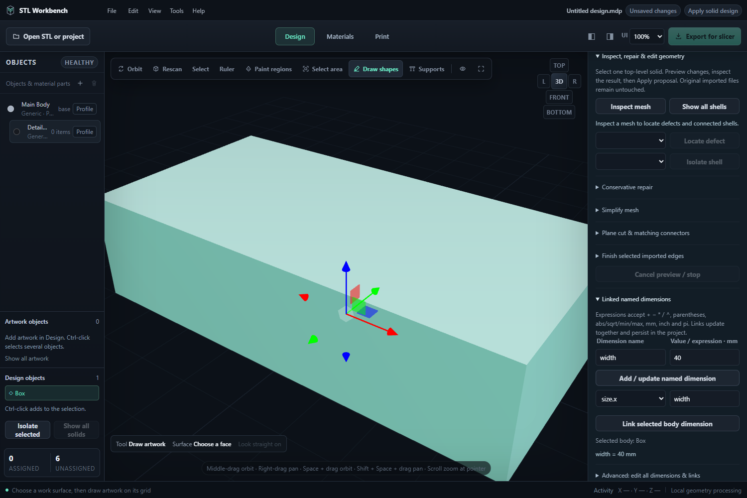
43. Configure the actual printer and inspect its plate
Start with Printer make and Model & feed setup above Objects in any workspace. Select a known printer/setup to apply it immediately, or Custom / other printer to enter the actual bed shape, dimensions and maximum height. The first selected printer centres the assembly and seats its bottom on the bed by default. No printer selected disables configured fit/placement while retaining the remembered values. New documents can reuse the last selected printer; opening an MDP restores that project's saved configuration.
Expand Dimensions & material feed to review the nozzle, Loaded material slots and Material feed. Manufacturer dimensions for a known preset are read-only here; use Custom for different physical dimensions. Apply edited fields with Apply printer settings. A circular custom bed uses Width / diameter for its diameter; it does not use the disabled Depth field.
Choose More printer settings, or in Print expand Printer & build volume, for origin, placement, offsets, clearance and hardware limits. Enable Check and place on this printer to use the configured fit/placement. Presets include their source and checking date. Confirm the actual printer dimensions and installed feeder configuration before relying on them.
- Bed shape, width/depth and maximum height define the usable rectangle or circular bed and vertical limit. Edge clearance reserves space around the perimeter.
- Origin chooses bed centre or front left. Placement either retains the assembly's X/Y coordinates or centres the entire assembly. Plate offsets move the whole assembly together. Seat whole assembly on Z=0 moves its bottom to the bed without moving individual material parts independently.
- Nozzle and filament diameter, loaded slots and material feed describe the configured hardware. Set abrasion resistance and actual temperature limits when known; blank temperature limits mean unknown.
Choose Apply printer & check fit. Findings check the complete exported assembly after enabled dimensional calibration, build orientation and common plate placement. Review out-of-bed, excessive-height, slot-capacity and feature-size findings. A fit result does not calculate supports or certify a print.
Inspect actual printer layout displays that transformed assembly with the configured cyan bed boundary and height indicator. Choose another tool to return to editing. Enabling printer placement also applies the same common transform to 3MF and aligned STL export, preserving material alignment. Leave the setting disabled for the original coordinate-preserving export workflow.
Distinguish the plate, drawing grid and material numbers
| Item | Purpose |
|---|---|
| Cyan printer plate boundary and grid | The actual configured rectangle or circle; in source-editing views its placement is mapped back from the same common export transform |
| Local work-surface grid | Artwork coordinates on the chosen face, including angled or side faces; it can occupy a different plane from the printer plate |
| Loaded material slots | Capacity of the configured hardware/feed setup, not a list of detected current spools |
| Slicer filament / tool number | Numbered material mapping carried from Material profile to the exported assembly |
| Physical printer location | Your saved feeder/tray/tool label; verify the corresponding mapping in the slicer |
The plate can be larger than the model's current close-up; zoom out to inspect its boundary, or use Inspect actual printer layout on the generated assembly. The grid is a visual aid and does not change the source geometry. The Printer setup selectors do not query the device, read AMS spools or synchronize a slicer automatically. Detect printers & loaded materials is a separate explicit read-only connection; only Use detected printer setup applies a recognized live model to this configuration.
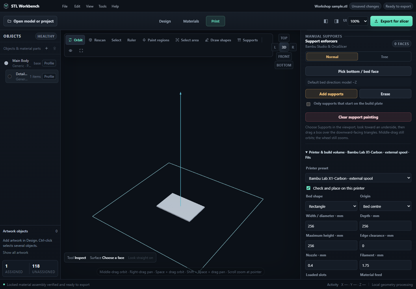
Supports no longer draws the arbitrary gold square. The support direction arrow remains a direction reference. The local work-surface grid is for drawing; the actual configured printer plate is for fit and export placement.
44. Exact section planes and material visibility
Build current material parts, then expand Section inspection in Print. Choose the build direction, X, Y, Z or a custom nonzero normal. Enter Plane coordinate in millimetres and Inspect this plane. Custom normals are normalized and use the same dot-product plane definition as the cut tool.
Previous layer and Next layer move by nominal layer height along the chosen plane normal. Along the build direction, an active adaptive-layer plan supplies its real planned boundaries. On X, Y or a custom plane these are inspection steps, not actual printer layers. The range display helps choose a plane intersecting the assembly.
Use Visible material parts to hide or show individual generated materials. This affects inspection only; it does not remove material from the model or export. It also filters the section preview. Return Explode inspection to zero for a true assembled section. The older percentage-based section slider remains available and returns to build-direction inspection.
The section shows exact geometry intersections with estimated walls/infill. It is a reference preview, not a generated slicer toolpath. Use the final slicer to verify printing layers, support and extrusion.
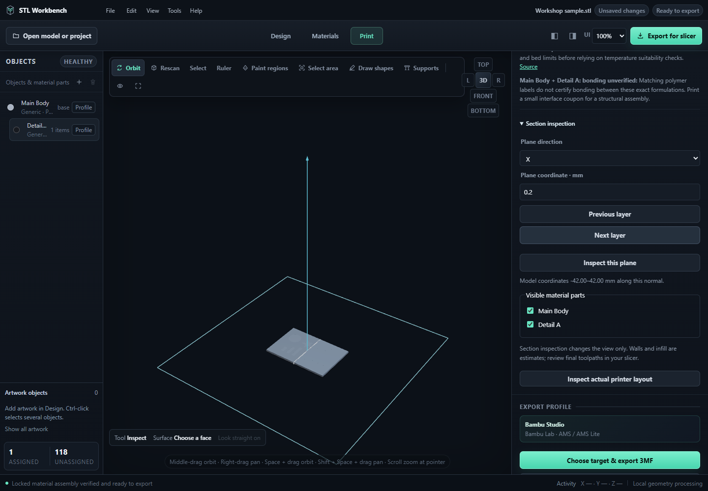
45. Import a multipart 3MF and open an installed slicer
Open or drop a 3MF using Open model or project. The import reads closed mesh bodies, component transforms, units and supported material assignments. It creates editable scene bodies and retains the material volumes, including interior inserts. Create material parts verifies the assembly before export. Later inlays replace the previous material in the new inlay volume; different existing materials cannot occupy overlapping solid volume.
Standard base materials, uniform triangle colours and supported Bambu, OrcaSlicer and PrusaSlicer facet-paint encodings are read. Subdivided painted facets retain their painted boundaries rather than recolouring the whole triangle. Original source bodies remain closed; imported paint is separate surface intent. Set each material's physical depth and create material parts to convert that paint into closed printable volumes. A slicer's painted colour does not by itself specify Workbench inlay thickness.
Interpolated colour gradients and unrecognized encodings receive an explicit import error. Missing resources, damaged topology or invalid transforms also stop import while retaining the current project. Slicer process settings and toolpaths are not imported as an editable Workbench process.
The separate feature editor now accepts a material assembly. Apply pending solid-design changes first. If the model has surface paint or artwork, opening the editor first builds and checks those material parts. Editable body chooses one closed body to edit while other bodies retain their geometry and materials. Show other bodies reveals the assembly context; Show material colours uses the material palette while feature selections remain highlighted. Fit all bodies frames the whole assembly after a body-specific close-up. Save an MDP in the editor to retain body-specific feature histories.
Returning the result evaluates the assembly together and keeps its material volumes. Paint and artwork used to create those bodies are then represented by the edited solids, rather than being applied a second time. The previous editable artwork and selections remain in Undo and checkpoints. If the original project changed while the editor was open, the return is rejected; save the edited project from the editor before resolving the competing changes.
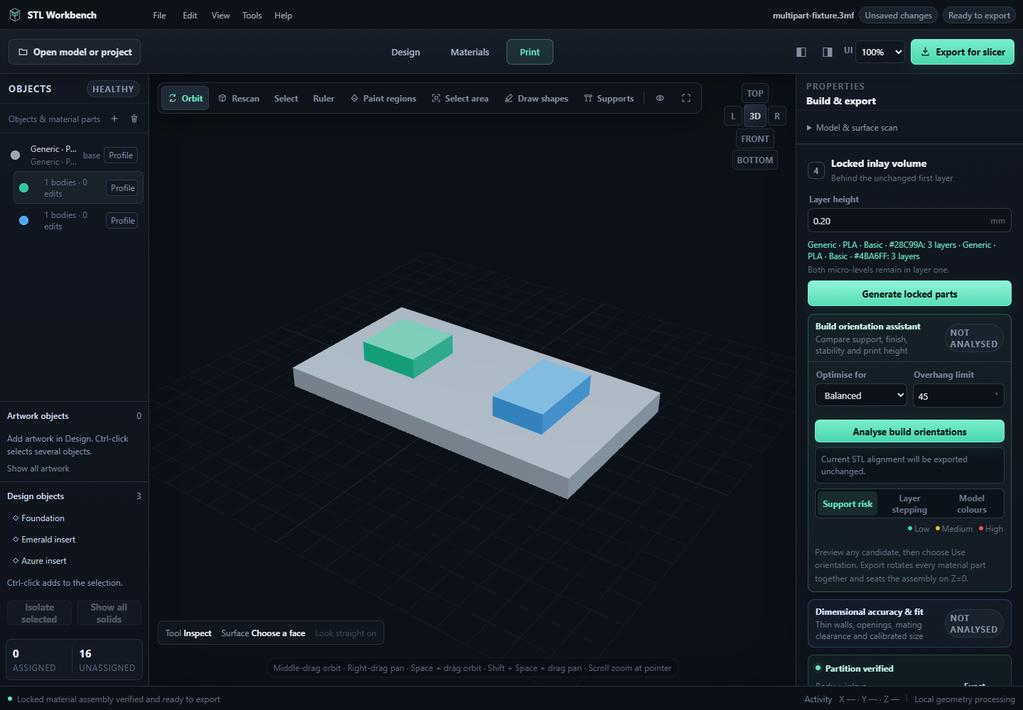
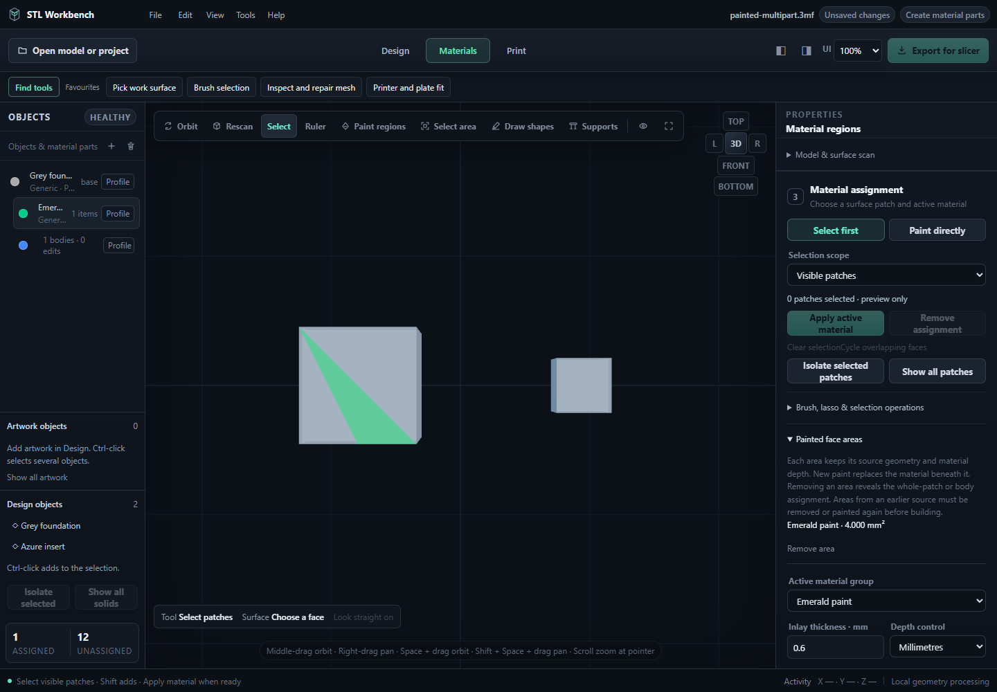
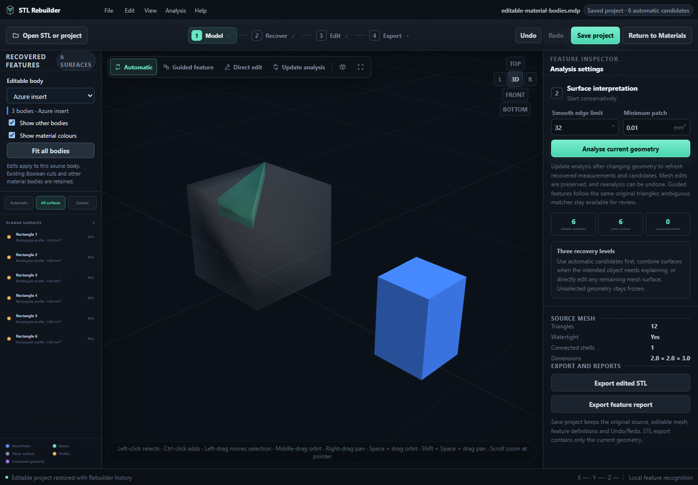
The Windows desktop edition adds Installed slicer application in Print's export area. Choose Bambu Studio, OrcaSlicer, PrusaSlicer or Cura. If automatic discovery fails, Choose installed application selects its executable. Enable Open in this slicer after 3MF export to launch it after a successful save. Open last exported 3MF reopens the current session's saved export.
Bring saved filament choices into the material editor
This shortcut is separate from Open model or project. It reads the saved filament list from a chosen 3MF while keeping the existing Workbench geometry:
- In Bambu Studio, choose the actual connected printer and review its loaded AMS filament types and colours. In Prepare, use the AMS filament synchronization / printer-information action and review its confirmation dialog. Labels vary with the Studio version and nozzle/feed setup.
- Save the slicer project as a 3MF after synchronizing. A sliced G-code export is not the saved project snapshot required here.
- In Workbench, open the intended Material profile, expand Choose materials from a slicer project and choose Load slicer materials…. Select the saved file. The model in that file is not imported by this command.
- Choose a Saved slicer filaments entry, read Imported settings notes, then Use selected filament. Check brand/type/colour and the Slicer filament / tool number. Enter the actual Physical printer location, then Apply material.
- Before printing, review the final slicer-to-AMS/tool mapping. If spools change, synchronize again, save a new project and reload its material snapshot.
Bambu Studio's synchronization separates filament type/colour from physical slot information, so Workbench does not infer an AMS tray from a saved filament index. Its official synchronization implementation describes this distinction. Bambu Studio filament synchronization
For PrusaSlicer, use File → Save Project as to save a project 3MF and load it through the same Workbench material shortcut. Prusa's tool/filament mapping can also remap project positions to actual MMU or tool positions. OrcaSlicer project 3MFs with the supported saved filament settings use the same shortcut. PrusaSlicer project saving, Prusa tool and filament mapping
This saved-project shortcut records saved settings only. It supplies no live printer connection, current spool verification or complete slicer process import. The separate desktop Detect printers & loaded materials dialog reads supported devices directly. Add material commits each usable reported slot as a project material while keeping that list open; Added prevents adding the same slot identity twice. Opening the list from an existing profile also offers Use in this profile for a cancellable draft. Physical feeder readings still need explicit slicer-number mapping. Missing manufacturer, formulation or colour information remains unknown; saved nominal temperatures are settings rather than measurements. Review any warnings and your actual spool before applying the profile.
If launch fails, the saved export remains available and the app reports the launch error separately. The browser edition downloads the file for manual opening and disables automatic application launch. In either route, review material-slot mapping and the final sliced result in the slicer.
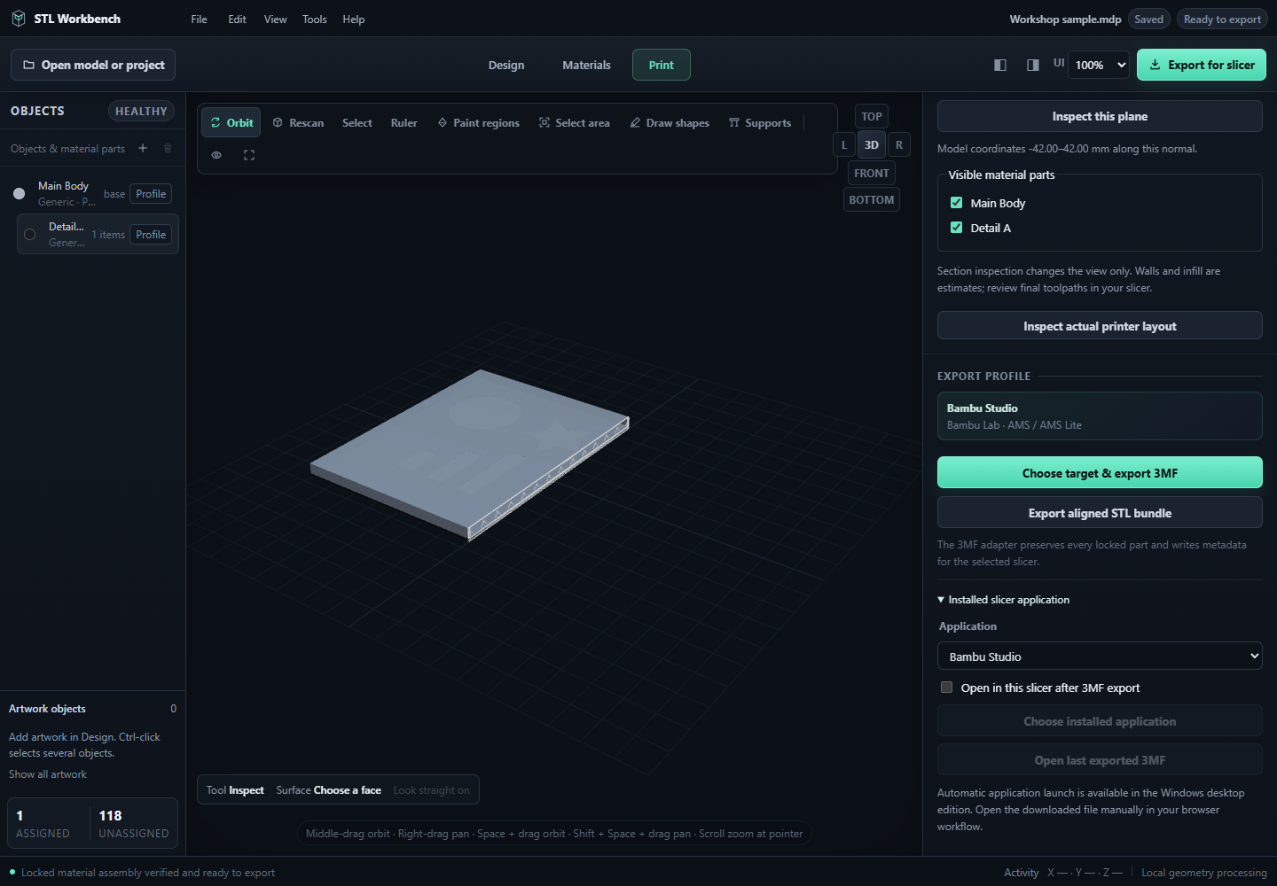
46. Named checkpoints and dated recovery history
Choose File → Checkpoints & recovery history. Enter a descriptive name such as Before cutting mounting sockets and Save named checkpoint. A checkpoint stores the complete editable MDP state, including scene, material bodies, drawings, linked dimensions, printer settings and undo history. It does not mark the working project as saved to a normal MDP file.
This project shows copies belonging to the current document; All projects helps locate an older document. Refresh history updates the dated list. Restore opens a saved copy after the normal save/discard/cancel prompt for unsaved work. Save an MDP after restoration to keep that revision as a normal project. Delete removes the selected snapshot after its confirmation; it does not change the open design.
Automatic recovery retains up to eight dated copies per project; named checkpoints have a separate retention allowance of forty per project. Storage is bounded, so very large projects can reach the local history budget. A recovery-history warning never substitutes for a completed manual MDP save. Snapshots are local to this computer/browser profile, not cloud backup. Save an MDP to another backed-up location when the project matters.
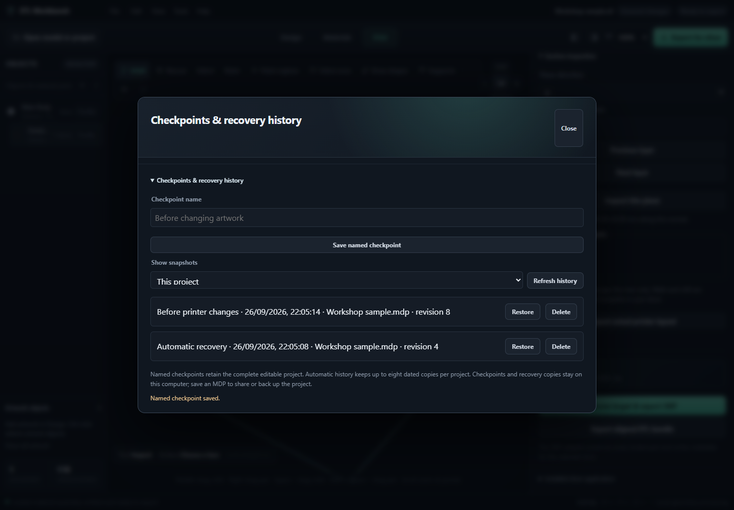
47. Material compatibility findings
Expand Material compatibility guidance within Printer & build volume. Read each finding with its evidence link. The checker compares supplied filament diameter, temperature ranges, configured printer limits, abrasion requirements and known feeder restrictions where documented. It also highlights non-overlapping recorded bed ranges and unverified bonding between the selected materials.
Unknown means there is insufficient evidence; it is not an approval. Community profiles and missing supplier limits remain distinguishable from manufacturer data. Matching PLA labels do not establish bonding between two exact formulations. Configure actual nozzle/feed hardware, check the product-specific supplier information and test an interface or fit coupon for a demanding assembly.
The findings are guidance stored with export metadata. They do not supply a verified profile for every combination of materials, automatic feeder generations or printer modifications. Continue using the final slicer's suitable printer/filament presets and inspect its output.
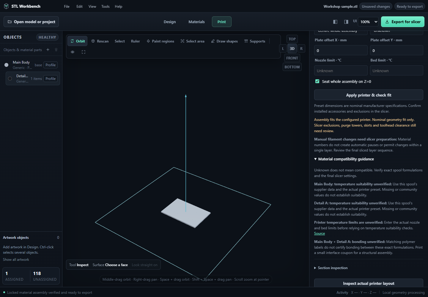
48. Find tools and keep favourites
Choose Find tools above the canvas, or press Ctrl+K. Type the task or control you need, such as brush, constraints, edge, section, printer or checkpoint. Results are grouped by Design, Materials, Print, Project and Help. Choose a group to narrow the list, or All to search across the application.
Select a result to switch to its workspace, activate the appropriate tool and reveal its inspector controls. A disabled result explains what is needed first, such as a selected artwork object or a generated assembly. Tool search does not create missing geometry or apply an edit automatically. For example, searching for cut opens the cutting controls so you can configure and inspect a proposal.
Select a result's star to pin it to the favourites row above the canvas. Select the star again to remove it. Up to eight favourites are retained on this computer/browser profile across restarts. Pinning is a personal interface preference; it does not change or dirty the project. Favourites in the search window shows just those tools. Arrow keys browse results, Enter chooses the focused result, and Escape closes the window and restores focus.
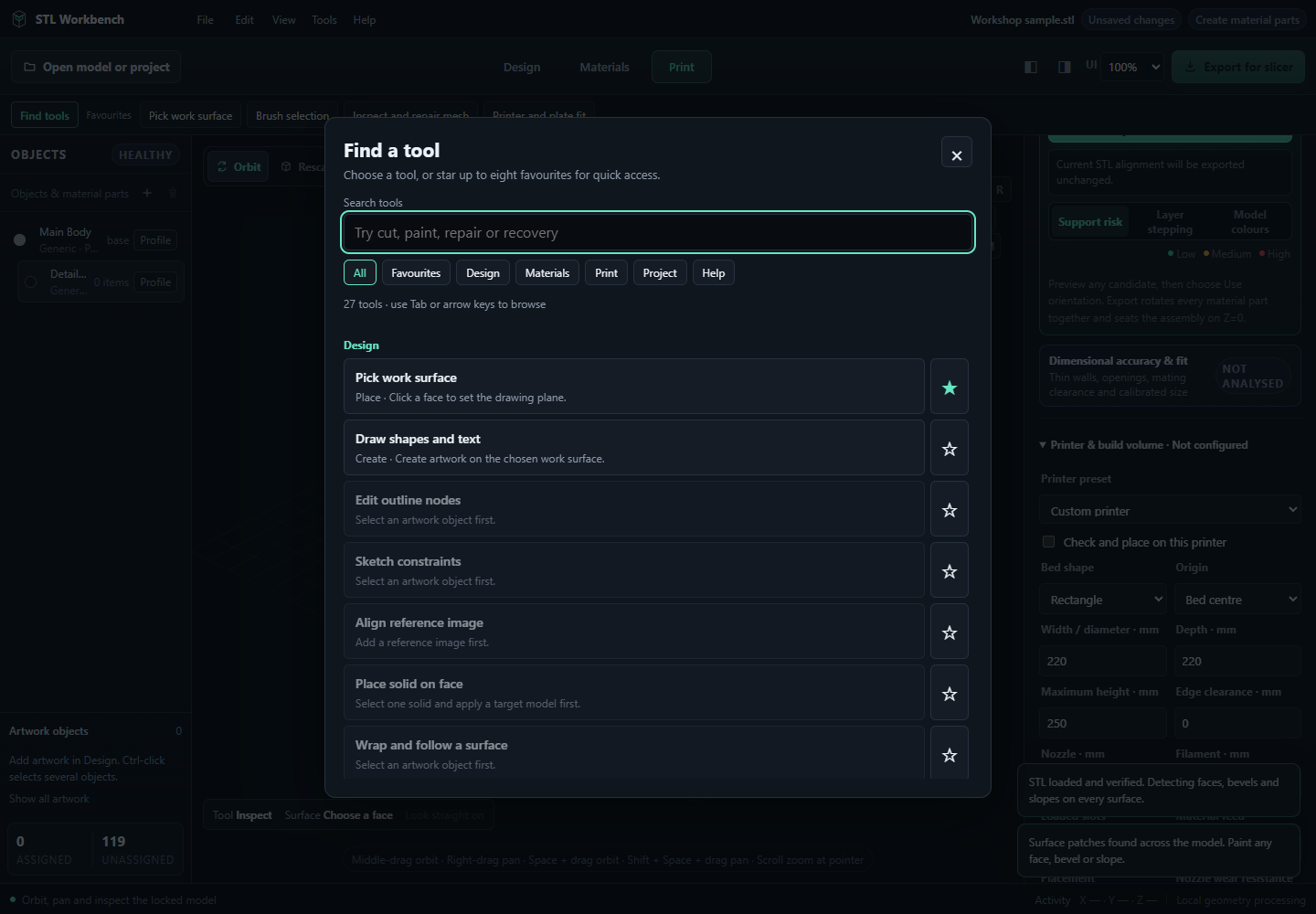
49. Constrain an editable sketch
Select one unlocked planar outline in Design, then expand Sketch constraints & dimensions. The outline's points and edges have persistent identities. Choose Relation or dimension, choose the first and second geometry where required, enter a value when shown, and select Add constraint. Positions and dimensions use the artwork's local millimetres; its overall placement and rotation remain separate.
Coincident points share a position. Horizontal and vertical relations constrain an edge to the local axes. Parallel, perpendicular and equal-length relations connect two edges. Point distance sets their separation; signed X and Y distances set a directional offset. Signed angle constrains the angle between edges. Circle radius changes the radius; tangency supports a line and circle or two circles, with an internal-circle option. Fix point holds its current local position.
The status reports remaining degrees of freedom. An under-constrained sketch can still move in the reported ways; fully constrained geometry has no remaining independent motion. A conflicting relation or drag is rejected and the previous valid outline remains. Redundant equations are identified separately from contradictory values. Add only the relationships needed for the intended shape.
Drag an outline node to solve the current relationships while moving it. Fixed or conflicting moves are refused. For a dimensional constraint, change its value in the saved list and choose Update. Remove deletes one relation and Remove all constraints releases them together. Undo restores a complete accepted change. MDP projects retain the sketch and relations.
The old width/height scaling controls and text regeneration are disabled while constraints are active because they would bypass the solved dimensions. Move and rotation remain available. Topology edits retain surviving point identities; removing a point also removes attached constraints. The solver edits polygon outlines and supported circles; it does not recover an imported STL's original parametric CAD model.
The geometry selectors name each edge's endpoint numbers and highlight the chosen geometry on the canvas while this panel is open. Circle relations use a fitted circular polygon boundary; an ellipse is not treated as a circle. Choose the matching geometry type for length, radius or tangency. Subdividing or curving an edge retains its existing relation as a construction-edge relation. Remove an active circle radius/tangency relation before changing that circle's topology. The solver is bounded to 160 points and 300 constraints; split more complex artwork into smaller editable sketches.
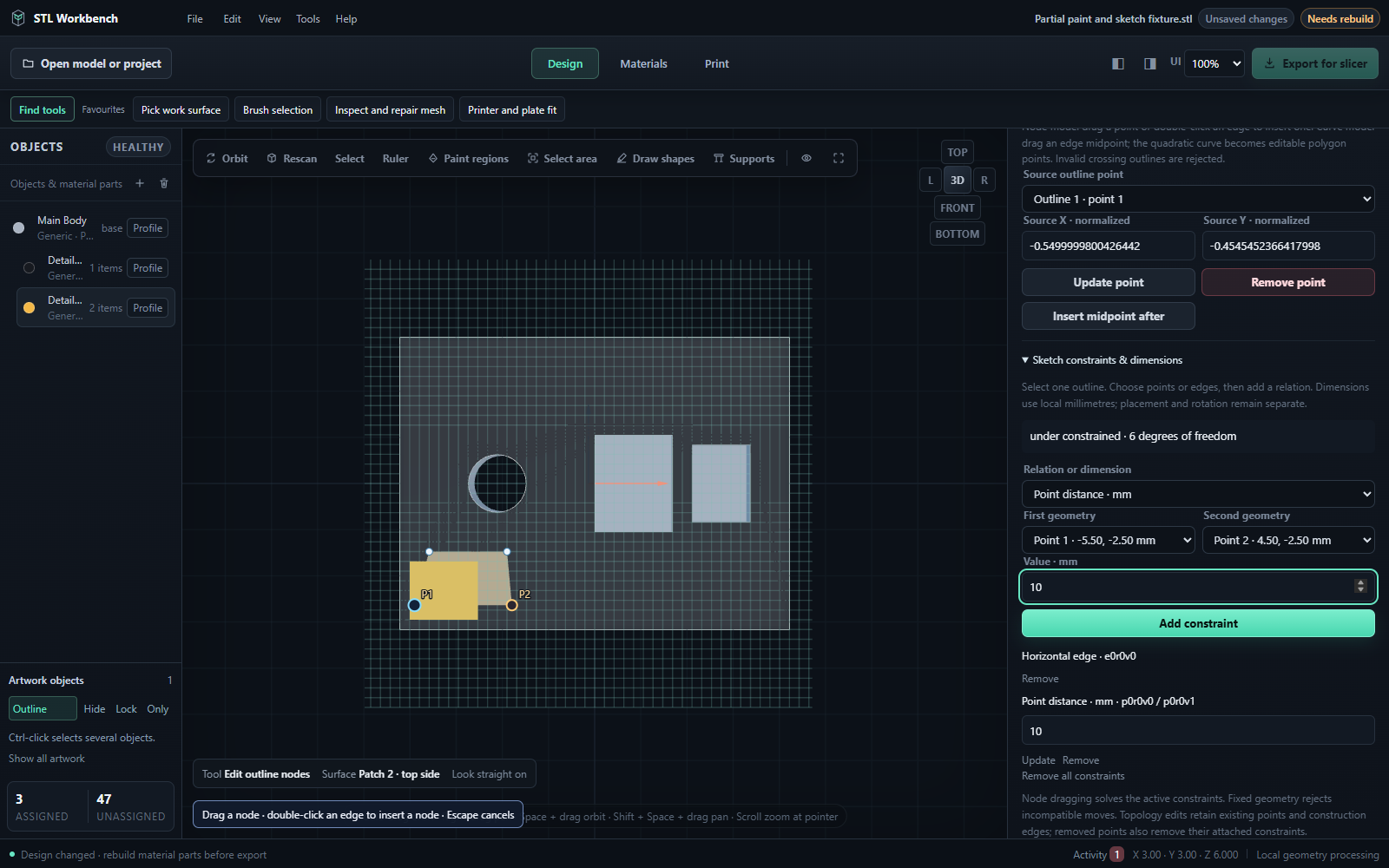
No matching chapters. Try a shorter word or clear your search.